Wall-following Moving Device

a moving device and wall-following technology, applied in the direction of distance measurement, process and machine control, instruments, etc., can solve the problems of adversely affecting the accuracy of the measured distance, the collision protection mechanism is not able to measure the distance between the robot b>90, > and the obstacle,

Inactive Publication Date: 2012-03-15
YU JYH CHENG +1
View PDF2 Cites 38 Cited by
  • Summary
  • Abstract
  • Description
  • Claims
  • Application Information

AI Technical Summary

Benefits of technology

[0016]The determining drive unit compares two signals reflected back from a wall and respectively received by the two signal transceiver units, and uses the intensity difference between the received signals as a basis to control the moving element to orientate the robot parallel to an obstacle. Triggered by the collision sensing units, the distance between the moving device and a wall can be precisely determined and controlled by an intricate coordination of the two signal transceiver units, the determining drive unit, and the moving element. The control error of the distance between the robot and an obstacle due to the variation of reflected signal intensity for different surface characteristics of the obstacle can be thus avoided.

Problems solved by technology

However, such collision protection mechanism is not able to measure the distance between the robot 90 and the obstacle when the robot 90 is away from the obstacle.
However, the size of the overlap area is determined by the intensity of the reflected signal that will still be affected by the surface characteristics of the obstacle to adversely influence the accuracy of the measured distance.
That is, while the prior art enables the robot to move parallelly along various types of wall, it does not ensure that a constant distance can be maintained between the robot and the wall.

Method used


Image

  • Wall-following Moving Device
  • Wall-following Moving Device
  • Wall-following Moving Device

Examples


Embodiment Construction

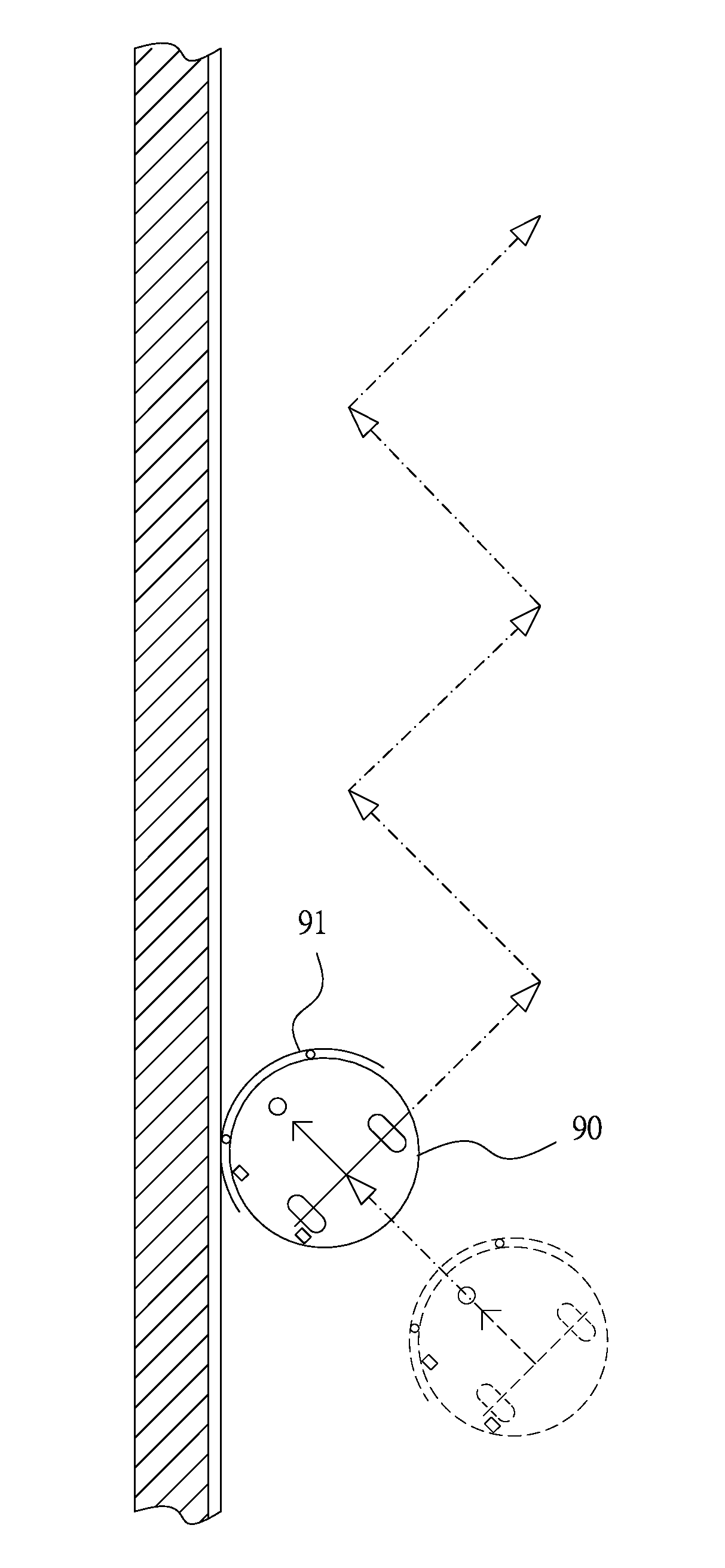
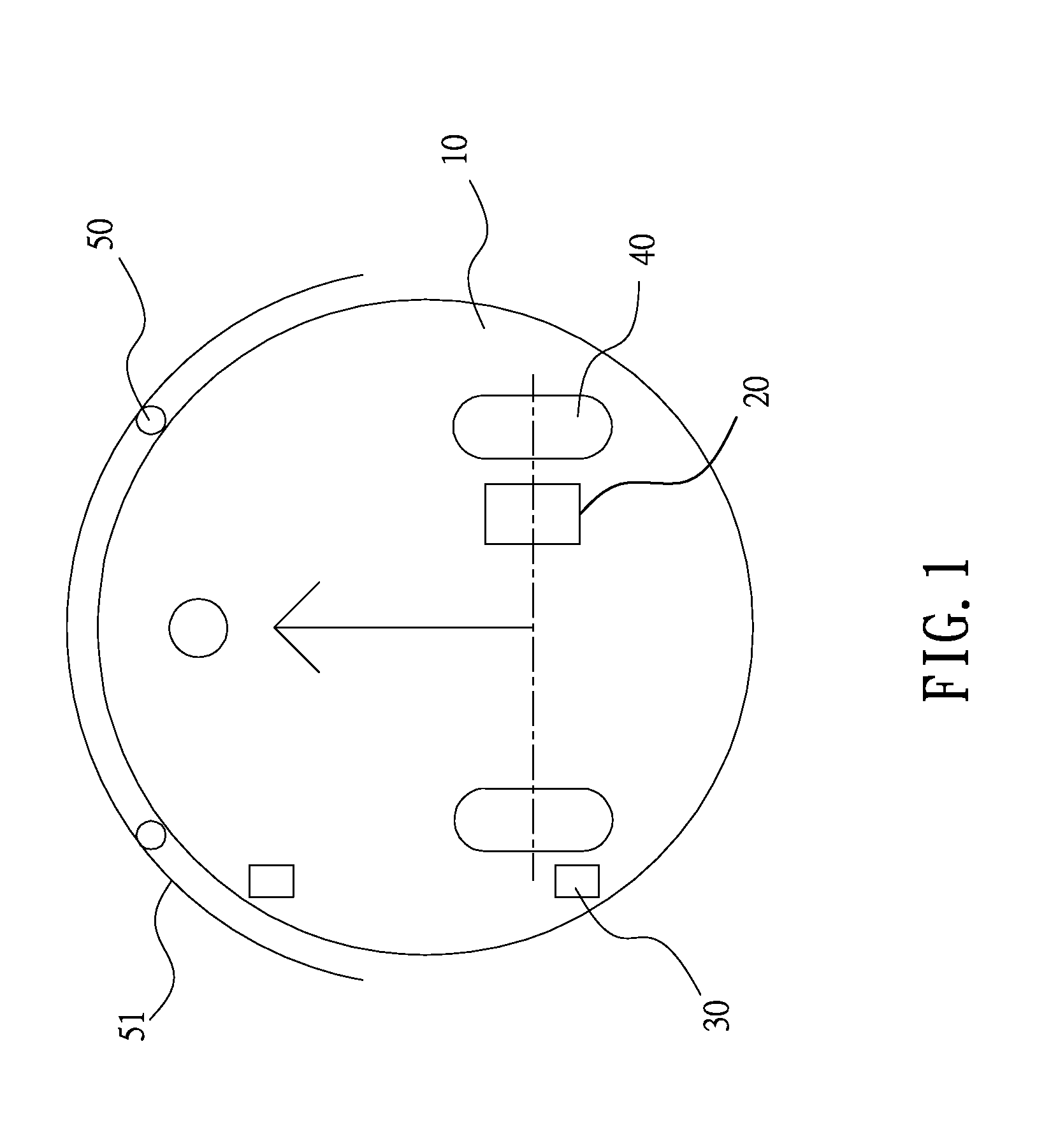
[0026]Please refer to FIG. 1 that is a schematic plan view showing the structure of a wall-following moving device according to a preferred embodiment of the present invention. The wall-following moving device of the present invention can be mounted to a bottom of a robot to control the robot moving indoors to move along an obstacle, such as a wall, with a constant distance from the obstacle, so that a cleaning robot, for example, can clean wall corners and perform other movements. As shown, the wall-following moving device according to a preferred embodiment of the present invention includes a base 10, a determining drive unit 20, two signal transceiver units 30, a moving element 40, and multiple collision sensing units 50. The base 10 is mounted to a bottom of a robot and may be circular.

[0027]The determining drive unit 20 is mounted on the base 10 and is an electronic device with multiple encoders connected to the moving element so as to serve as a motion central control unit. Wh...


PUM


Abstract

A wall-following moving device consists of a base; a determining drive unit; multiple collision sensing units; two signal transceiver units arranged at the same lateral side of the base parallel to the moving direction of the base for synchronously transmitting and receiving specific signals, and being electrically connected to the determining drive unit; and a moving element mounted to the base and controlled by the determining drive unit to perform various movements. The determining drive unit compares two reflected signals from a wall received separately by two signal transceiver units, and uses the intensity difference of the signals as a basis to control the moving element to orientate the robot parallel to the wall. By an intricate coordination of the collision sensing units, two signal transceiver units, determining drive unit, and the moving element, the distance between the robot and a wall can be precisely determined and controlled.

Description

BACKGROUND OF THE INVENTION[0001]1. Field of the Invention[0002]The present invention relates to a wall-following moving device, which is mounted on a robot for controlling the robot to move parallelly along an obstacle, such as a wall.[0003]2. Description of the Prior Arts[0004]The application technique of an automated product, such as a mobile robot, for domestic chores has gradually become mature. The mobile robot, such as a cleaning robot or a security robot, when being used indoor, is often required to move along an obstacle, such as a wall, in a constant distance so as to clean corners, locate entrances and exits, or search for a charging base.[0005]According to most of the existing techniques for controlling the robot to move along a wall, when the robot collides against the wall, a control integrated circuit (IC) calculates to thereby drive the robot to move backward, adjust to a correct moving direction, and then move forward again. For the robot to perform movements in the...

Claims


Application Information

Patent Timeline
Patent Type & Authority Applications(United States)
IPC IPC(8): G05D1/03
CPCG05D1/0227G05D1/0242G05D2201/0203G05D1/0272G05D1/0255
Inventor YU, JYH-CHENGYAN, JASON
Owner YU JYH CHENG
Why Eureka
Try Eureka