

Bank angle detecting device for vehicle
- Summary
- Abstract
- Description
- Claims
- Application Information
AI Technical Summary
Benefits of technology
Problems solved by technology
Method used
Image

Examples
second embodiment
[0119]The bank angle estimator 59A of the bank angle detecting device 19A includes a calibrating bank angle detector 86, a first dividing circuit 88, a third subtracting circuit 92, a second adding circuit 94, an angular velocity integrating circuit 62 and a feedback line 96. The calibrating bank angle detector 86 is operable to calculate a motorcycle body bank angle δ1 for calibration purpose with reference to an output ωy of the yaw component sensor 55B, which output ωy is corrected by a yaw component subtracting circuit 87B as will be described later, and the velocity v of the motorcycle measured by the velocity sensor 57. The third subtracting circuit 92 is operable to generate a difference (δ1−δ) between the body bank angle δ1 for calibration purpose and the estimated bank angle δ outputted from the angular velocity integrating circuit 62 and the first dividing circuit 88 is operable to divide this difference (δ1−δ) by a time T. The second adding circuit 94 is operable to add ...
third embodiment
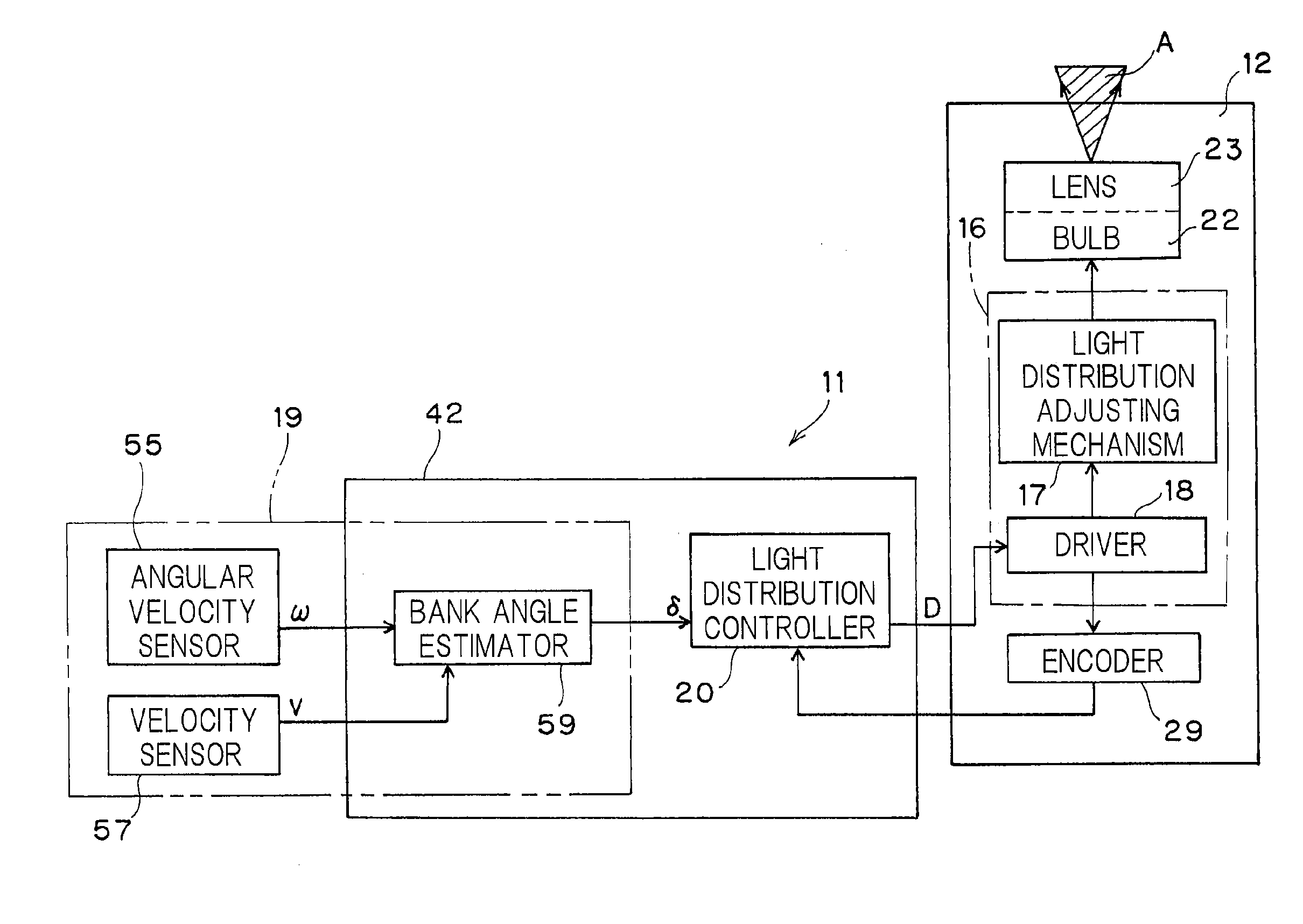
[0121]FIG. 11 illustrates a circuit block diagram showing the headlamp device 11A according to a third preferred embodiment of the present invention. According to this third embodiment, the light distribution controller 20 controls the light distribution adjusting mechanism 16 with the estimated roll rate P used as a lamp velocity command D. Based on the angular velocity ω outputted from the angular velocity sensor 55, the roll rate estimating circuit 60 generates an estimated roll rate P, which is in turn outputted to the angular velocity integrating circuit 62. The angular velocity integrating circuit 62 performs a time integration of the estimated roll rate P to calculate the estimated bank angle δ. The bank angle δ so obtained is used in any suitable application such as, for example, a circuit for restricting an engine torque by, for example, an excessive bank angle as will be described later.
[0122]According to the first embodiment shown in and described with particular referenc...
PUM
 Abstract
Description
Claims
Application Information