Hybrid heat exchanger apparatus and method of operating the same

a heat exchanger and hybrid technology, applied in lighting and heating apparatus, ventilation systems, heating types, etc., can solve the problems of inability to emit plumes in closed circuit coolers, undesirable heat exchangers, and water being considered scarce and valuable resources, and achieve the effect of inhibiting the formation

Inactive Publication Date: 2012-03-22
EVAPCO
View PDF10 Cites 44 Cited by
  • Summary
  • Abstract
  • Description
  • Claims
  • Application Information

AI Technical Summary

Benefits of technology

[0014]It is an object of the invention to provide a hybrid heat exchanger apparatus that might inhibit...

Problems solved by technology

As a result, a heat exchanger that spews a visible plume P of water condensate is undesirable.
First, particularly in cold climates, closed circuit coolers can emit plume when th...

Method used


Image

  • Hybrid heat exchanger apparatus and method of operating the same
  • Hybrid heat exchanger apparatus and method of operating the same
  • Hybrid heat exchanger apparatus and method of operating the same

Examples


Embodiment Construction

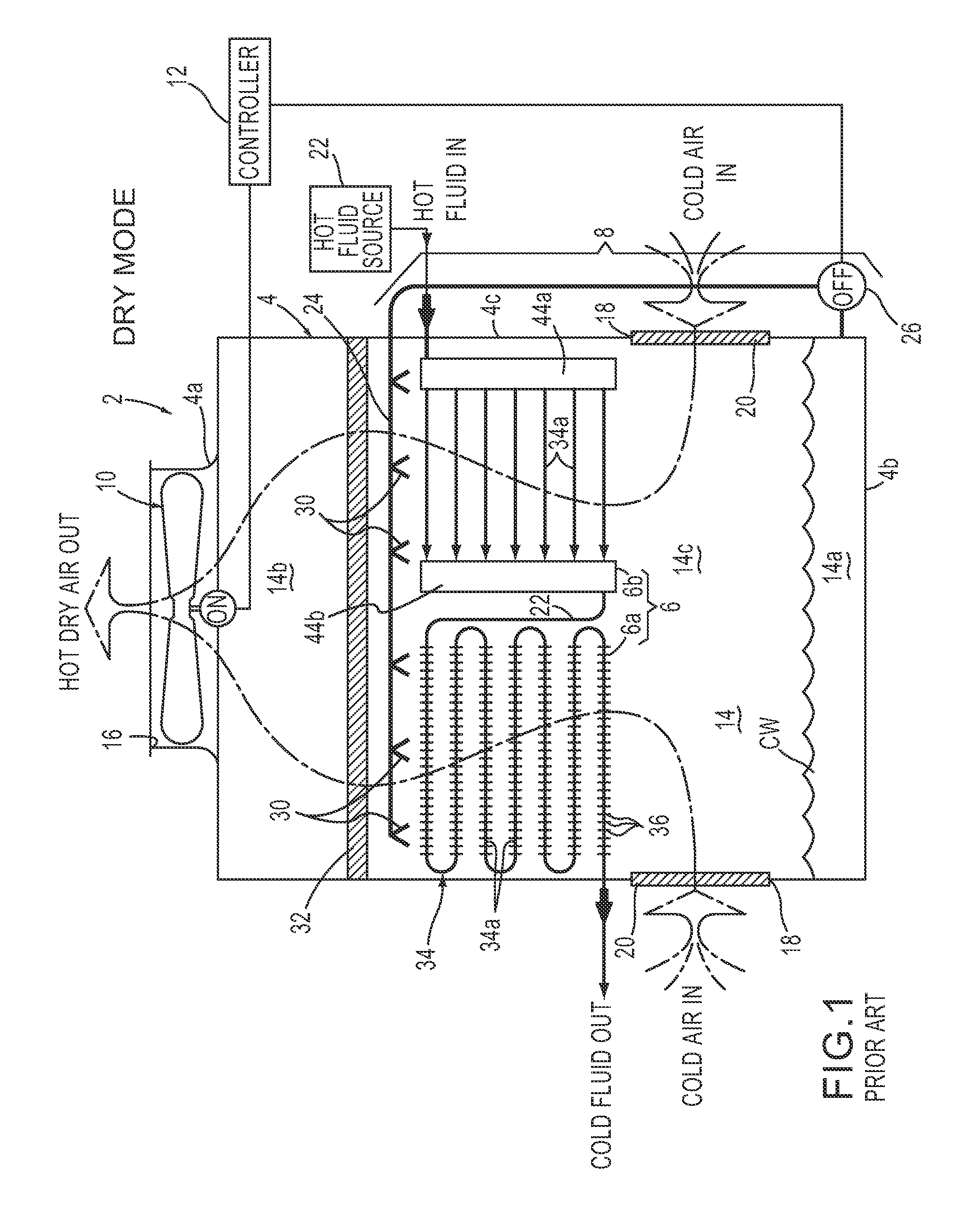
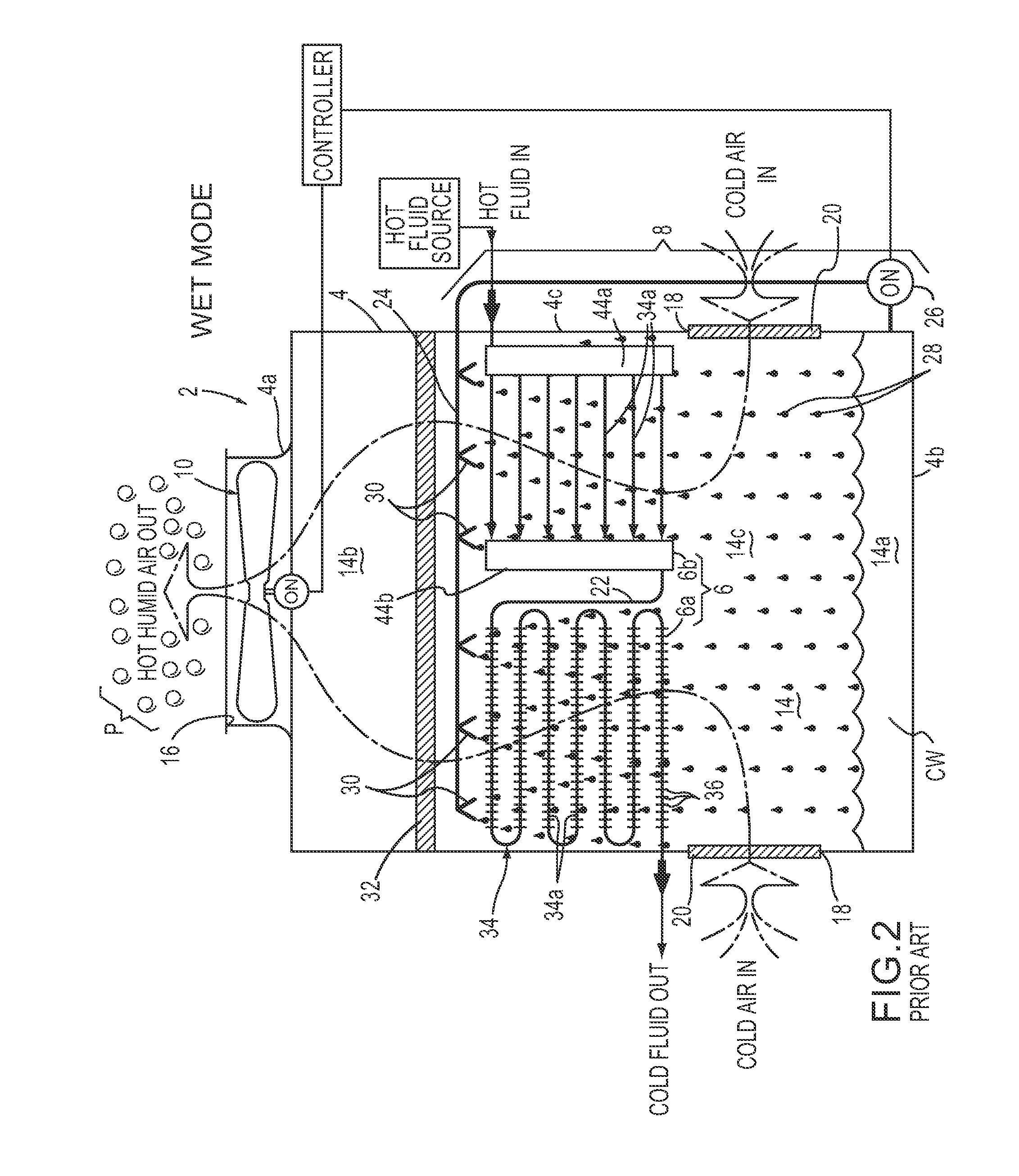
[0041]Hereinafter, exemplary embodiments of the present invention will be described with reference to the attached drawing figures. The structural components common to those of the prior art and the structural components common to respective embodiments of the present invention will be represented by the same symbols and repeated description thereof will be omitted. Furthermore, terms such as “cold”, “hot”, “humid”, “dry”, “cooling” and the like shall be construed as relative terms only as would be appreciated by a skilled artisan and shall not be construed in any limiting manner whatsover.

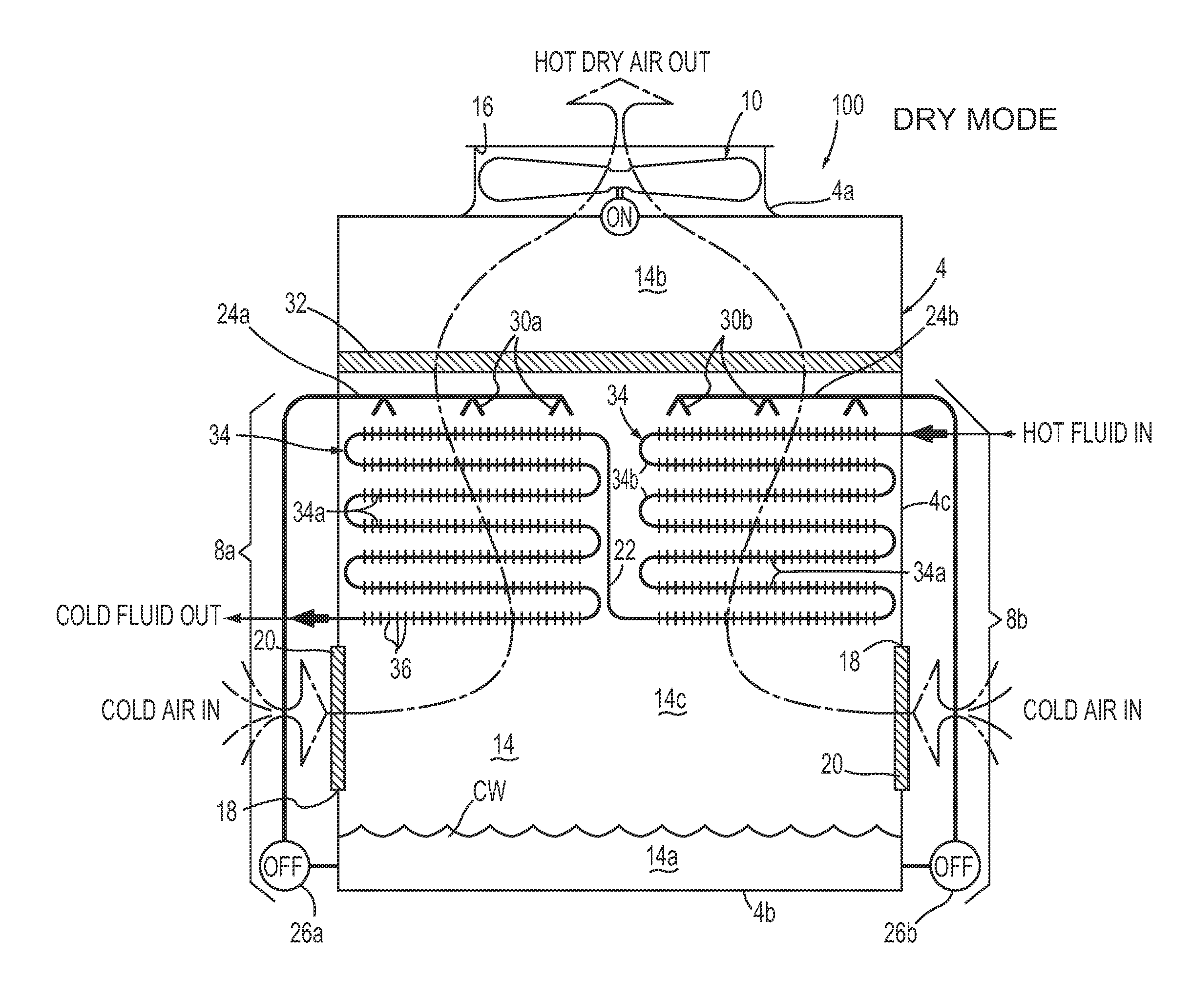
[0042]A first exemplary embodiment of a hybrid heat exchanger apparatus 100 of the present invention is hereinafter described with reference to FIGS. 3-5. As shown in FIGS. 3-5, the hybrid heat exchanger apparatus 100 includes a first cooling water distribution system 8a and a second cooling water distribution system 8b. The first cooling water distribution system 8a has a first water distribution...


PUM


Abstract

A hybrid heat exchanger apparatus having a heat exchanger device with a hot fluid flowing therethrough includes a cooling water distribution system and an air flow mechanism for causing ambient air to flow across the heat exchanger device. The cooling water distribution system distributes evaporative cooling water onto the heat exchanger device to wet only a portion of the heat exchanger device while allowing a remaining portion of the heat exchanger device to be dry. The air flow mechanism causes ambient air to flow across the heat exchanger device to generate hot humid air from the ambient air flowing across the wet portion of the heat exchanger device and hot dry air from the ambient air flowing across the remaining dry portion of the heat exchanger device. Methods are also described.

Description

FIELD OF THE INVENTION[0001]The present invention relates to a hybrid heat exchanger apparatus. More particularly, the present invention is directed to a hybrid heat exchanger apparatus that operates in a dry mode, a wet mode and a hybrid wet / dry mode in order to conserve water and, possibly, abate plume.BACKGROUND OF THE INVENTION[0002]Heat exchangers are well known in the art. By way of example, a conventional heat exchanger 2, sometimes referred to as a “closed-circuit cooler”, is diagrammatically illustrated in FIGS. 1 and 2. The heat exchanger 2 includes a container 4, a heat exchanger device 6, a cooling water distribution system 8, an air flow mechanism such as a fan assembly 10 as illustrated and a controller 12. The container 4 has a top wall 4a, a bottom wall 4b and a plurality of side walls 4c. The plurality of side walls 4c are connected to each other and connected to the top wall 4a and the bottom wall 4b to form a generally box-shaped chamber 14. The chamber 14 has a w...

Claims


Application Information

Patent Timeline
IPC IPC(8): F24F7/00F28F9/24F28F1/20F24F3/14F28F9/02
CPCF24F5/0035F28C1/14F28C1/16F28D1/0417Y02B30/545F28D1/0477F28D1/05316F28D3/02F28D5/02F28D1/0461F28C2001/145
Inventor BUGLER, III, THOMAS W.VADDER, DAVEY J.
Owner EVAPCO
Why Eureka
Try Eureka