
Interception system that employs miniature kill vehicles

an interception system and miniature technology, applied in direction controllers, instruments, weapons, etc., can solve the problems of large aperture d of the ir imaging sensor fitted thereon, large kv of present kill vehicles, complicated and thus expensive, etc., and achieve the effect of increasing the kill probability

Inactive Publication Date: 2012-03-22
ISRAEL AEROSPACE IND
View PDF17 Cites 7 Cited by
  • Summary
  • Abstract
  • Description
  • Claims
  • Application Information

AI Technical Summary

Benefits of technology

[0007]According to certain embodiments of the invention, the sensors that are employed in a Miniature Kill Vehicle (MKV) are in the visible or near IR spectrum instead of the IR part thus significantly improving the resolution for a given aperture by an order of magnitude. Visible or near IR sensors are also much smaller than the IR ones, they provide high resolution with a small aperture and they do not need cooled focal plane arrays. All this reduces the weight and cost of the sensor dramatically and it releases the requirements imposed on the divert system time constants allowing the MKV to maneuver more efficiently. Since the targets do not emit enough energy in the visible or near IR part of the spectrum, some illumination device should be added to the system.
[0031]In accordance with a certain embodiment of the invention there is yet further provided an interceptor missile, wherein at least two KVs are launched towards the same RV with a time delay between planned interceptions to increase the kill probability.

Problems solved by technology

Present Kill Vehicles (KV) are quite large, complicated and thus expensive.
These sensors are quite large and expensive.
Due to the small size of each MKV, the aperture d of the IR imaging sensor fitted thereon cannot be large.
The specified degraded resolution may result in missing the sweet spot thereby reducing the prospect of successful kill.
In addition, the degraded resolution may lead to an undesired result of failing to identify that the “target” that the MKV tracks is in fact two (or more) real targets (since due to the degraded resolution the MKV cannot distinguish between the two) and therefore even if it succeeds in hitting one of the targets the other or others (non distinguishable) targets could leak and hit the friendly territory leading to dire consequences.

Method used


Image

  • Interception system that employs miniature kill vehicles
  • Interception system that employs miniature kill vehicles
  • Interception system that employs miniature kill vehicles

Examples


Embodiment Construction

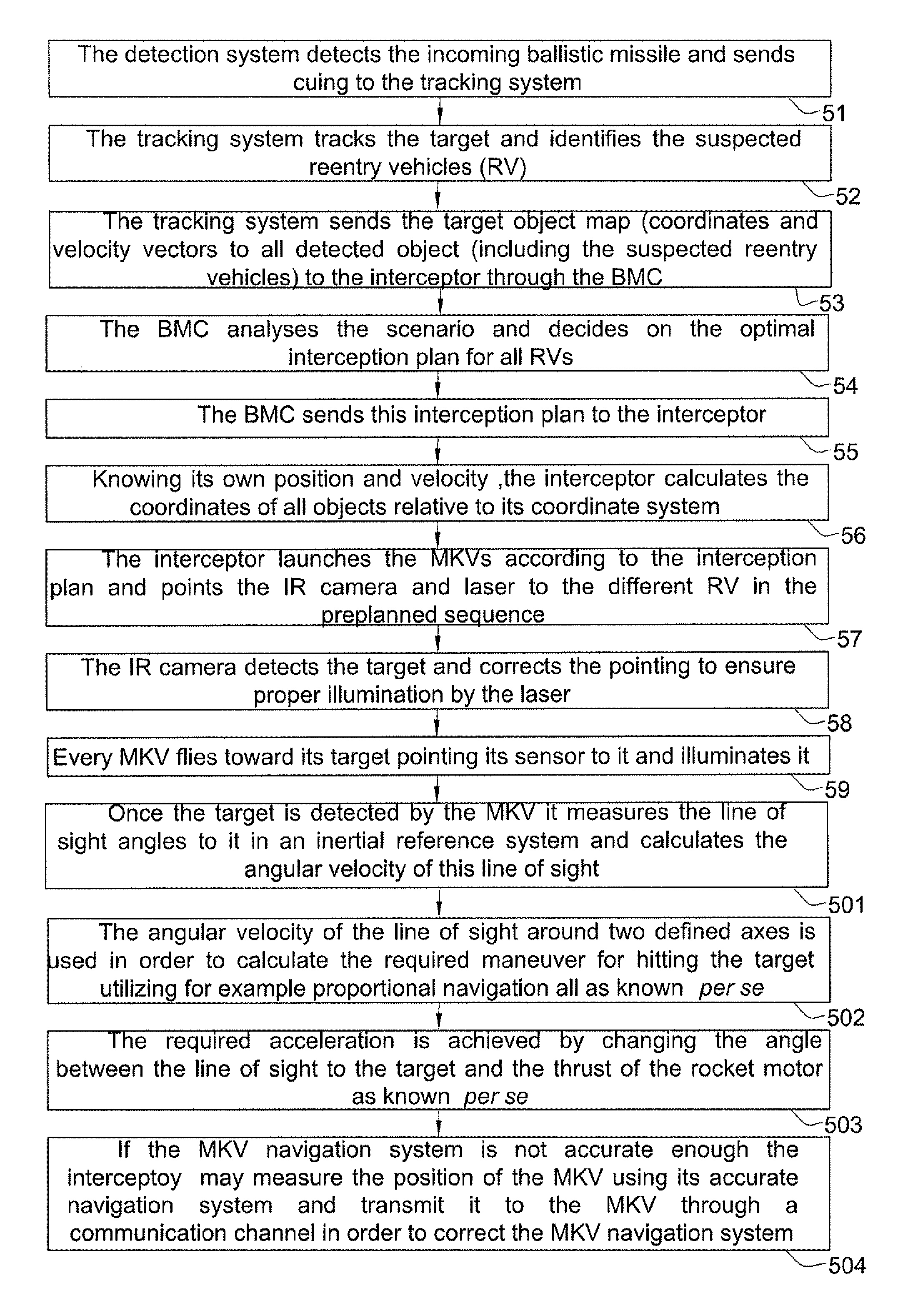
[0046]In accordance with certain embodiments, when a threat is launched towards a friendly territory a known detection and tracking system detects the object, tracks it and a battle management center (BMC) classifies it as a potential threat and in response launches one or more interceptor missiles towards the threat(s). The threats are one or more Re-entry Vehicles (RV) associated with the Ballistic Missile (BM).

[0047]Having launched an interceptor missile, it has, as is known per se, a bus system for controlling its flight and the mission plan (of destroying the threat or threats) based on a mission plan communicated thereto and being updated whenever necessary.

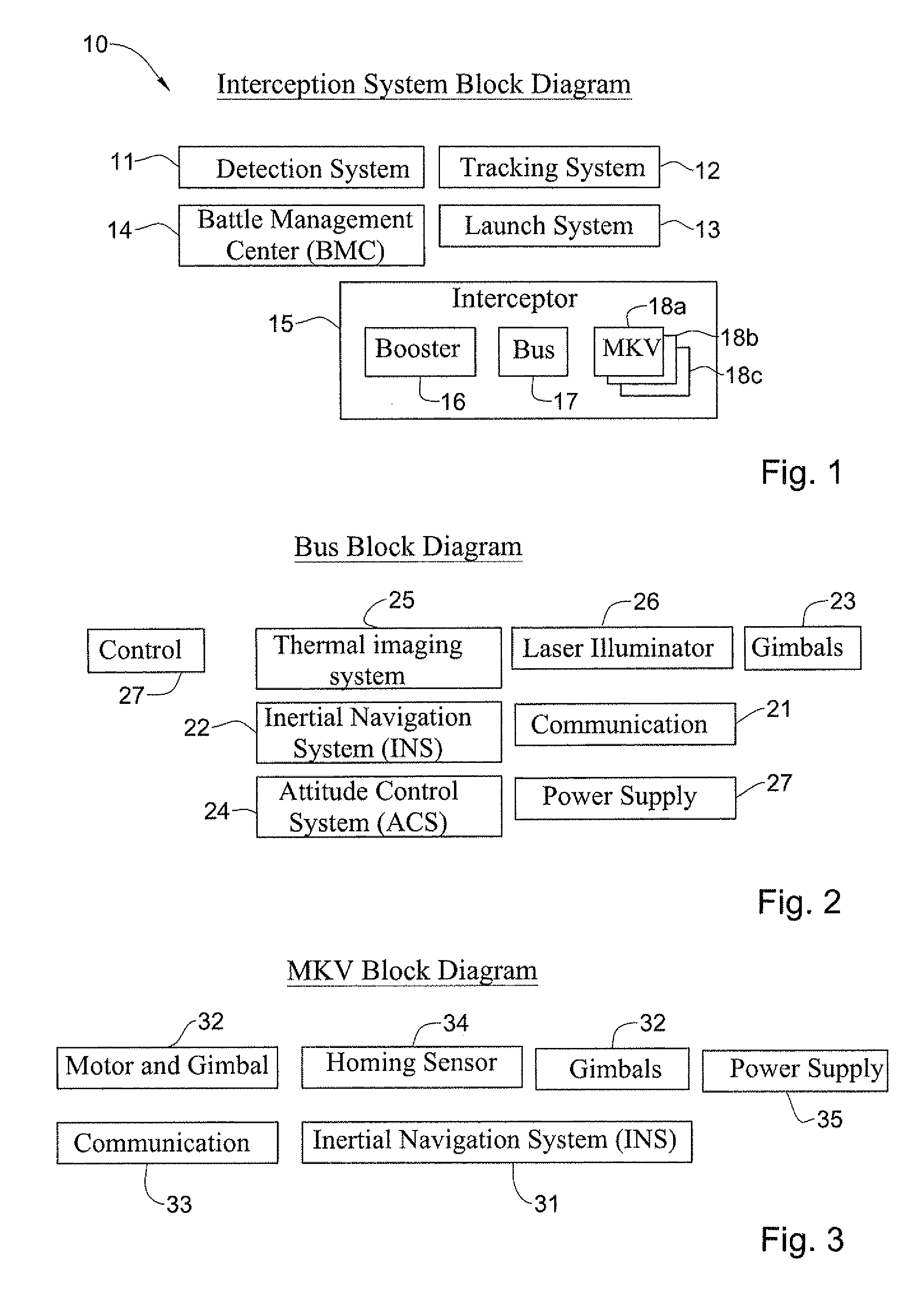
[0048]Bearing this in mind, attention is drawn to FIG. 1, illustrating a block diagram of an interception system architecture, fitted in typically (although not necessarily) in a ground station 10, in accordance with certain embodiments of the invention. As shown, the system includes a detection system 11a Tracking system 1...


PUM


Abstract

There is provided an interception system that employs miniature kill vehicles. According to certain embodiments of the invention, a small kill-vehicle (KV) accommodated within an interceptor missile together with additional at least one KV, each KV is equipped with an image acquisition sensor operable in the visible or near IR range, and adapted to be launched from the interceptor missile during exo-atmospheric flight and utilizing said sensor for tracking and homing at least one Re-entry Vehicle (RV) of a Ballistic Missile (BM).

Description

FIELD OF THE INVENTION[0001]This invention relates to a method and system for employing multiple kill vehicles (KV) designated to kill multiple Re-entry Vehicles (RVs) that are launched simultaneously towards a friendly territory.BACKGROUND OF THE INVENTION[0002]Ground to ground ballistic missiles (BM) have become an efficient weapon which can cause significant damage to military and civilian infra-structures, and thereby they serve as a strategic tool in favor of states which attack their enemies (either offensively or defensively as a result of an attack originated by the enemy). In light of this ever increasing threat, an anti missile technology has been developed, such as the “Arrow” anti-missile technology (deployed and used by the Israel Defense Forces) and others. The Arrow system is capable of tracking the oncoming ground to ground BMs and launch, e.g. from a protected territory, an interceptor missile which flies along a flight trajectory which substantially intercepts that...

Claims


Application Information

Patent Timeline
IPC IPC(8): F42B15/01F42B15/10
CPCF41H11/02F42B15/01F42B12/62
Inventor GOLDNER, GALYAHASSON, JOSEPH
Owner ISRAEL AEROSPACE IND
Learn More