Method and Apparatus for Measuring the Optical Forces Acting on a Particle

a particle and optical force technology, applied in the direction of optical elements, instruments, masers, etc., can solve the problems of inability to measure forces on non-spherical samples, inability to make measurements with non-gaussian laser beams, and system impractical commercial us

Active Publication Date: 2012-03-22
MONTES USATEGUI MARIO +1
View PDF3 Cites 13 Cited by
  • Summary
  • Abstract
  • Description
  • Claims
  • Application Information

AI Technical Summary

Problems solved by technology

This is a complex procedure that requires specialized equipment (piezo actuators) and human expertise which make the systems impractical for commercial use.
There are a number of other problems associated with the “indirect” single-beam methods.
First, it is not possible to measure forces on non-spherical samples.
Second, it is not possible to make measurements with non-gaussian laser beams because these do not produce harmonic potentials.
Third, it is not possible to make measurements in non-homogeneous media, which limits the feasible experiments essentially to those performed in vitro.
An important example is experiments inside living cells, which are not possible since the optical properties of the cytosol change from point to point.
Moreover, the use of duplicated optical components makes these systems expensive and more difficult to operate.
An important point is that the opinion among those skilled in the art is that the use of single-beam traps for measuring forces using the “direct” method is impossible.

Method used


Image

  • Method and Apparatus for Measuring the Optical Forces Acting on a Particle
  • Method and Apparatus for Measuring the Optical Forces Acting on a Particle
  • Method and Apparatus for Measuring the Optical Forces Acting on a Particle

Examples


Embodiment Construction

[0037]In the following description, numerous specific details are set forth in order to provide a thorough understanding of the present invention. It will be understood, however, to one skilled in the art, that the present invention may be practiced without some or all of these specific details. In other instances, well known process operations have not been described in detail in order not to unnecessarily obscure the present invention. It is also important to note that the accompanying drawings are not drawn to scale.

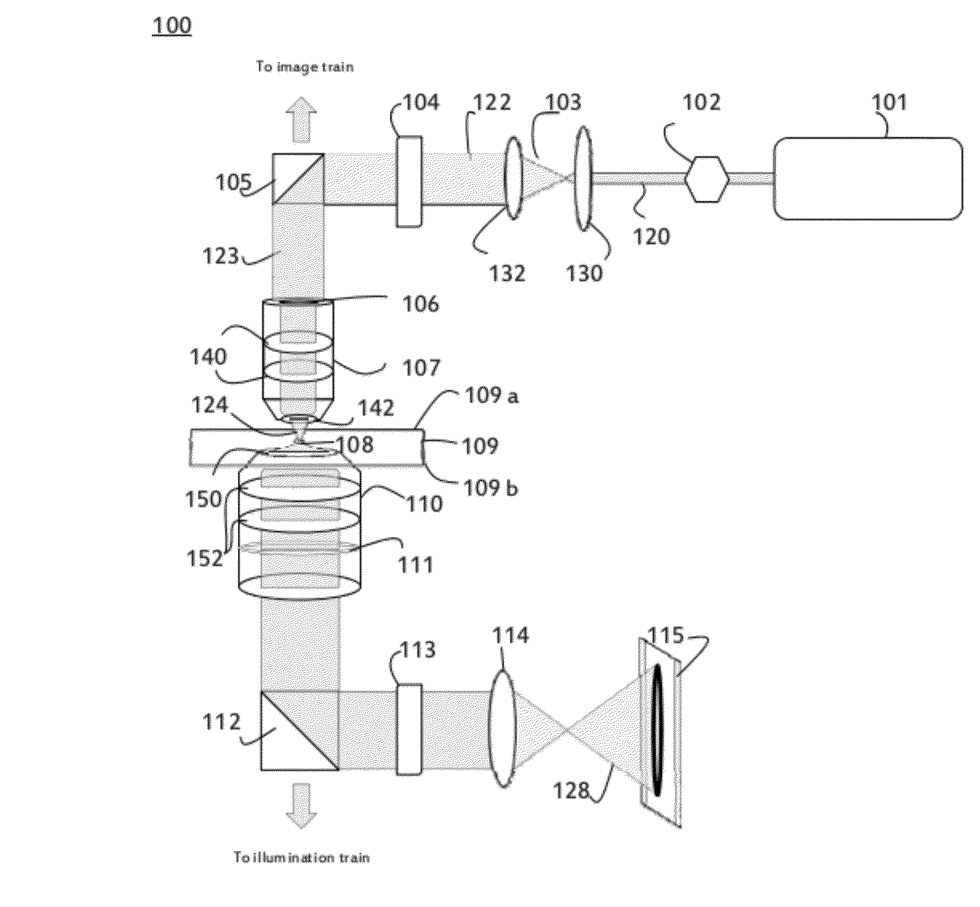
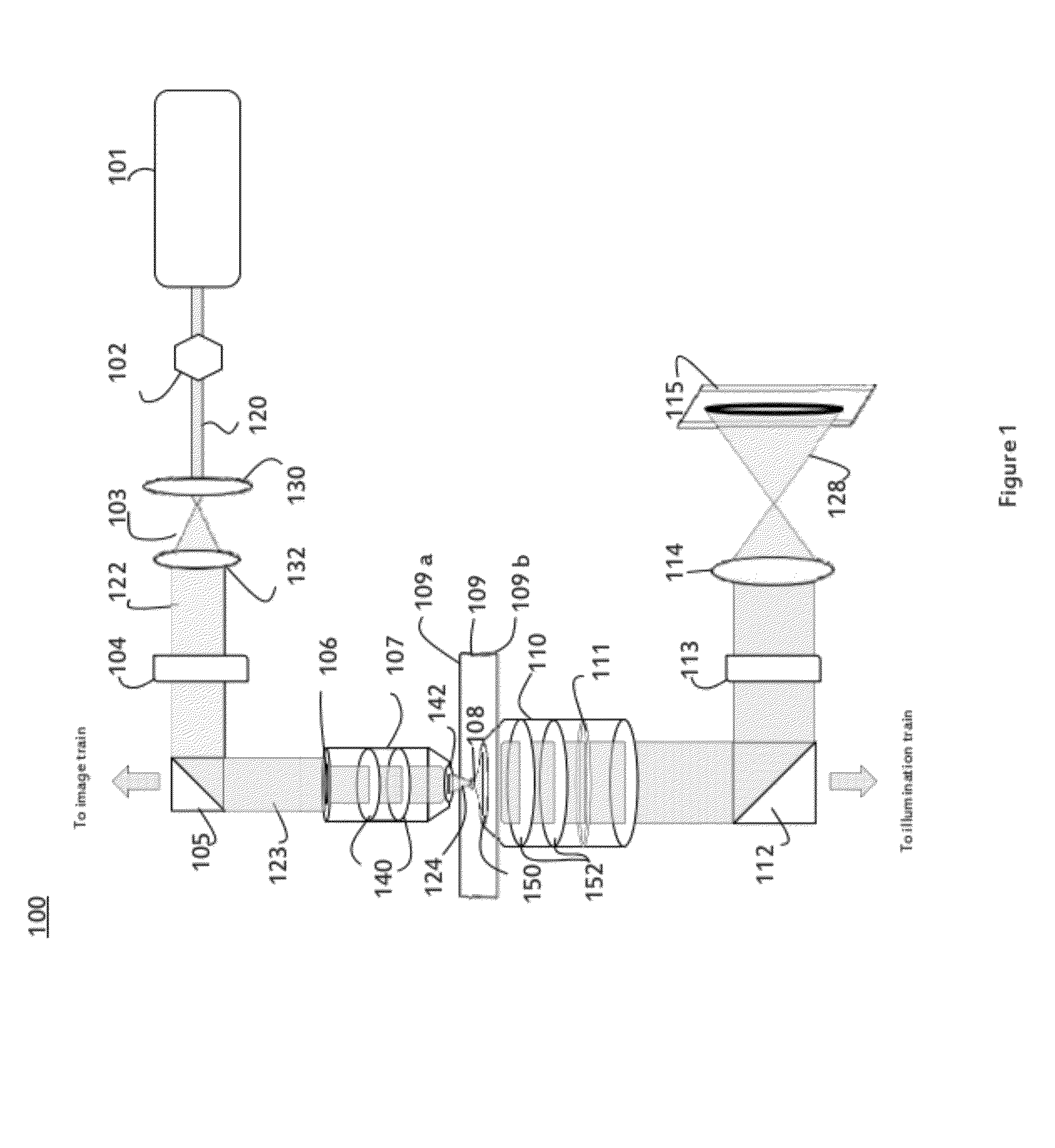
[0038]FIG. 1 illustrates a system 100 for measuring optical forces acting on a particle 108 in accordance with one implementation of the present invention. System 100 includes a chamber 109 for suspending a particle 108 in a suspension fluid between an entry cover 109a and an exit cover 109b which are typically made of glass. Trapping of particle 108 is achieved by focusing a light beam 124 on the suspended particle with the use of a high numerical aperture trap objec...


PUM


Abstract

An apparatus and method for measuring optical forces acting on a trapped particle. In one implementation the apparatus and method are adaptable for use in the optical train of an optical microscope that is configured to trap, with a single light beam, a particle suspended in a suspension medium between an entry cover and an exit cover of a chamber positioned on or within the microscope. The apparatus and method involves the use of a single collection lens system having a numerical aperture designed to be greater than or equal to an index of refraction index of the suspension medium intended to suspend the particle in the chamber which is placeable at or near the exit cover of the chamber of the microscope. A light sensing device is positioned at or near the back focal plane of the collection lens, or at an optical equivalent thereof, which is capable of directly or indirectly producing optical force measurements acting on the particle derived by the x and y coordinates of the centroid of the light distribution imaged onto the light sensing device by the collection lens.

Description

[0001]The invention relates to a system and methods for measuring optical forces acting on a microscopic sample, and more particularly to a system and methods for determining the force components acting on a trapped particle in an optical tweezers assembly.BACKGROUND ART[0002]There are essentially two prior art methodologies, “indirect” and “direct”, for measuring optical forces acting on a trapped microscopic sample. The indirect methods generally have in common the use of a single-beam laser which require the use of complex mathematical models of the trap (harmonic potential) and of the environment (fluid with a homogeneous index of refraction and viscosity, under low Reynolds number conditions) to determine forces acting on a sample that must be spherical in form. The method of indirectly measuring forces on a trapped sample is disclosed in Svoboda, K. & Block, S. M. “Biological Applications of Optical Forces”, Annual Review of Biophysics and Biomolecular Structure Vol. 23, pp. 2...

Claims


Application Information

Patent Timeline
Patent Type & Authority Applications(United States)
IPC IPC(8): H01S1/00G02B21/32
CPCG02B21/32G01L1/25G21K1/06
Inventor MONTES USATEGUI, MARIOFARRE FLAQUER, AMAU
Owner MONTES USATEGUI MARIO
Why Eureka
Try Eureka