
Eureka
For R&D, Eureka makes reading and utilizing patents & technical documents easy.
Eureka AIR
Designed for self-driven R&D workflows. Generate viable solutions, solve complex R&D challenges, empower your innovation with AI.

Eureka Materials
Designed for material experts only. Revolutionize your material R&D, from search, analyze, to developing new materials.

TechResearch
Generate reliable direction feasibility study reports for your R&D in just a few steps.

TechSeek
Discover and master advanced knowledge NOW. Basics, ideas, possibilities, all at once.

TechMind
As an expert in R&D Theories, TechMind can generates customized viable solutions instantly.

TechRisk
Analyze your overall solution with one click, know your potential R&D risks in advance.

TechMonitor
Get weekly tech updates, stay abreast of the latest tech innovations and key insights.
Switch module for an electric machine having switchable stator windings
- Summary
- Abstract
- Description
- Claims
- Application Information
AI Technical Summary
Problems solved by technology
Method used
Image

Examples
Embodiment Construction
[0008]A detailed description of one or more embodiments of the disclosed apparatus is presented herein by way of exemplification and not limitation with reference to the Figures.
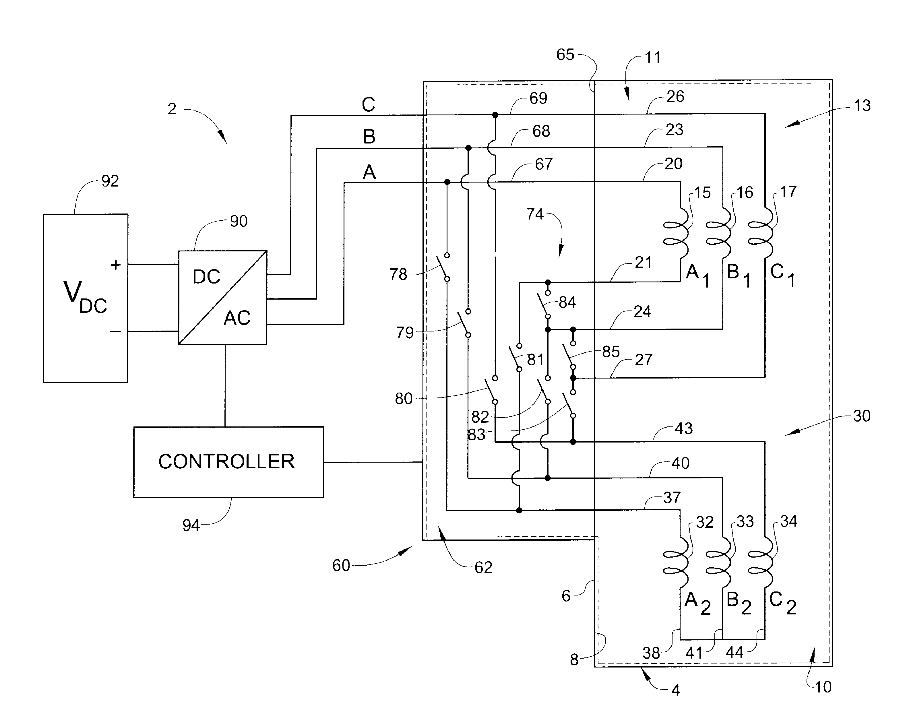
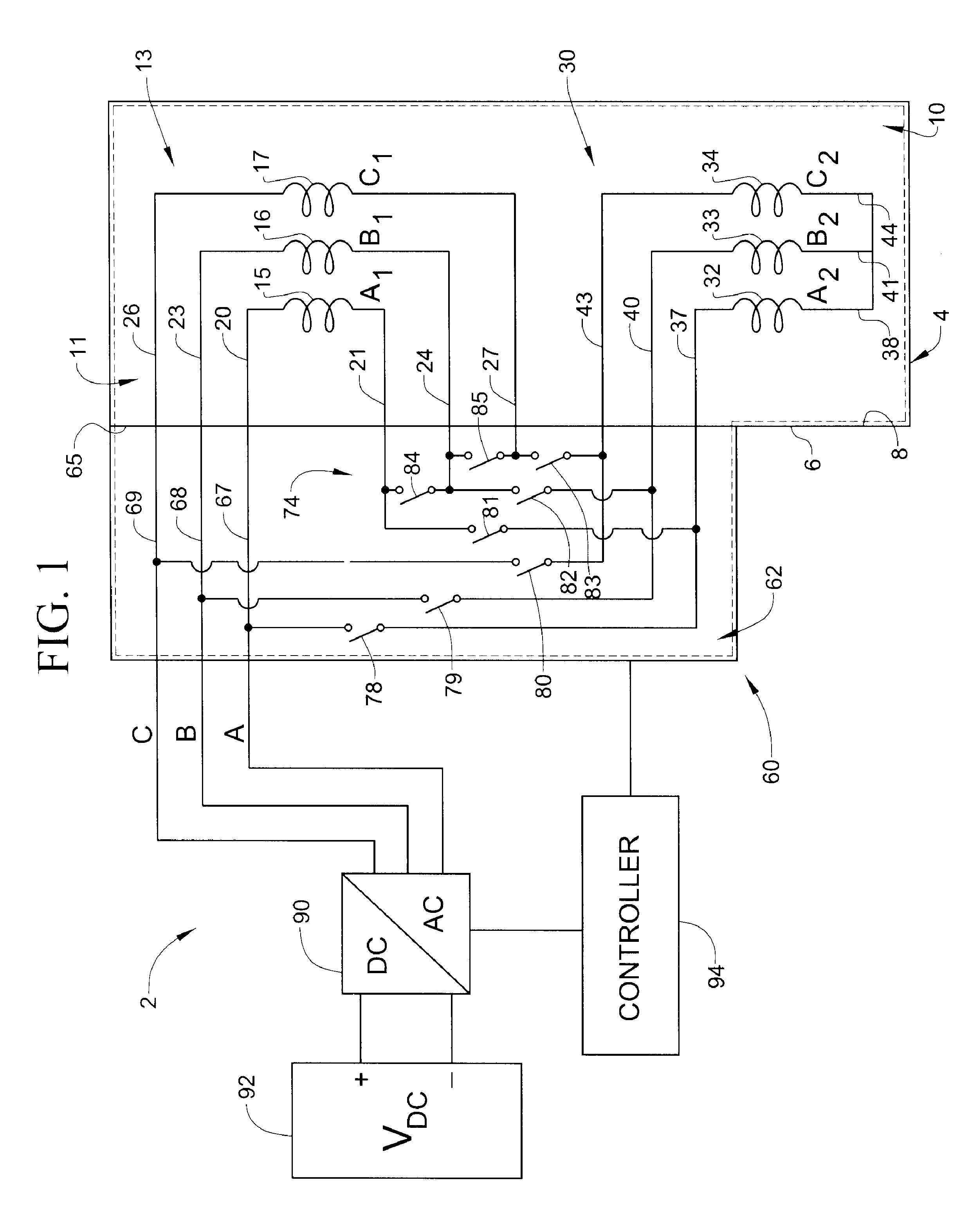
[0009]An electric machine, shown in the form of an electric motor, in accordance with an exemplary embodiment is indicated generally at 2. Electric machine 2 includes a housing 4 having an exterior surface 6 and an internal surface 8 that defines an interior portion 10. Electric machine 2 includes a stator 11 including a first plurality of windings 13. First plurality of windings 13 includes three windings A1, B1, and C1 shown at 15-17 respectively. Winding 15 includes a first lead or conductor 20 and a second lead or conductor 21. Similarly, winding 16 includes a first lead 23 and a second lead 24, and winding 17 includes a first lead 26 and a second lead 27. Stator 11 is also shown to include a second plurality of windings 30. Second plurality of windings 30 includes three windings A2, B2, and C2 shown at ...
PUM
 Abstract
Description
Claims
Application Information
 - R&D Engineer
- R&D Manager
- IP Professional
- Industry Leading Data Capabilities
- Powerful AI technology
- Patent DNA Extraction
Browse by: Latest US Patents, China's latest patents, Technical Efficacy Thesaurus, Application Domain, Technology Topic, Popular Technical Reports.
© 2024 PatSnap. All rights reserved.Legal|Privacy policy|Modern Slavery Act Transparency Statement|Sitemap|About US| Contact US: help@patsnap.com