
Permanent magnet electric motor

a permanent magnet electric motor and permanent magnet technology, applied in the field of electric motors, can solve the problems of pmdc motors that are not suitable for small electric apparatuses with a compact structure and cannot be reduced in siz

Inactive Publication Date: 2012-03-22
JOHNSON ELECTRIC SA
View PDF6 Cites 0 Cited by
  • Summary
  • Abstract
  • Description
  • Claims
  • Application Information

AI Technical Summary

Benefits of technology

"The present invention provides a permanent magnet electric motor with a rotor and stator, and a commutator for controlling the magnetic field. The motor has a unique design with a rotor core and windings connected in a triangular configuration. The commutator has a small size and is connected to the stator through short circuit wires. The motor can be used in a lens driving device. The technical effects of the invention include improved motor performance and reduced size and weight of the motor."

Problems solved by technology

The size of the commutator cannot be reduced, which results in a kind of PMDC motor that is not suitable for small electric apparatus with a compact structure.

Method used


Image

  • Permanent magnet electric motor
  • Permanent magnet electric motor
  • Permanent magnet electric motor

Examples


Embodiment Construction

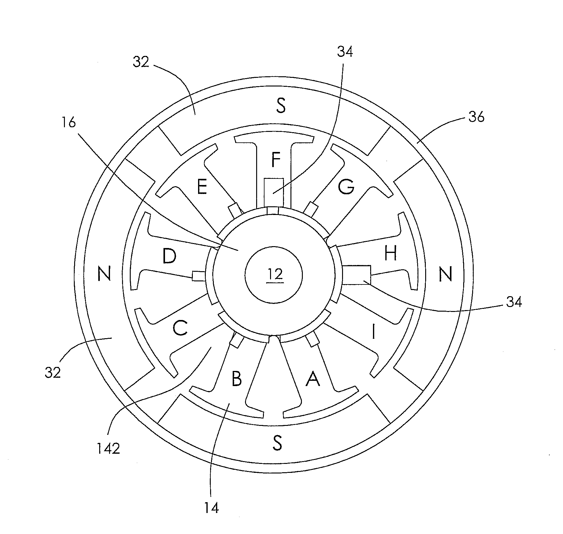
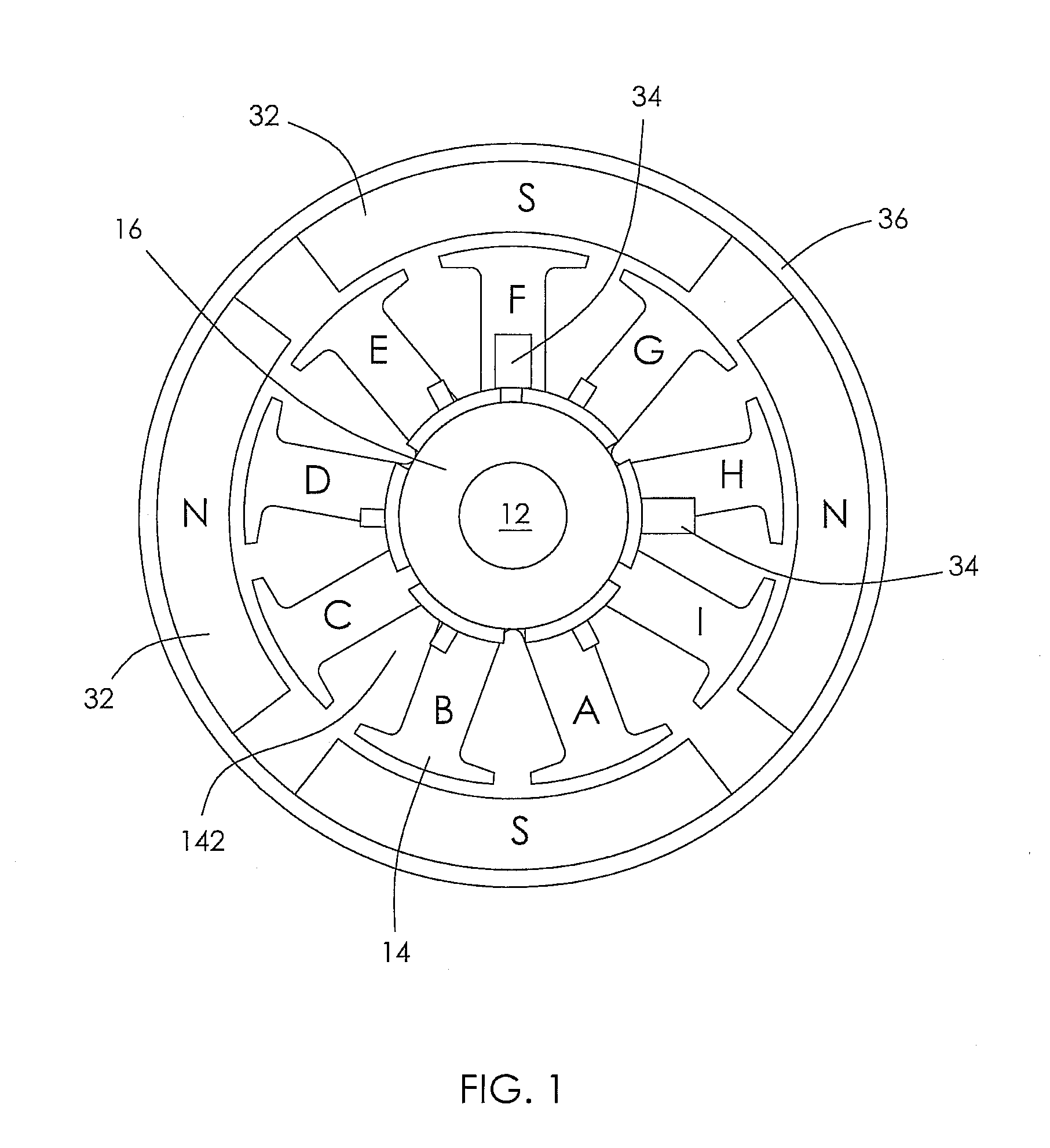
[0019]A permanent magnet electric motor according to a preferred embodiment of the present invention is shown in the figures of the drawings. In FIG. 1 the rotor windings are omitted to simplify the drawing and to show more clearly the structure and shape of the rotor core. As shown in FIG. 1 the motor comprises a rotor and a stator magnetically coupled to the rotor.

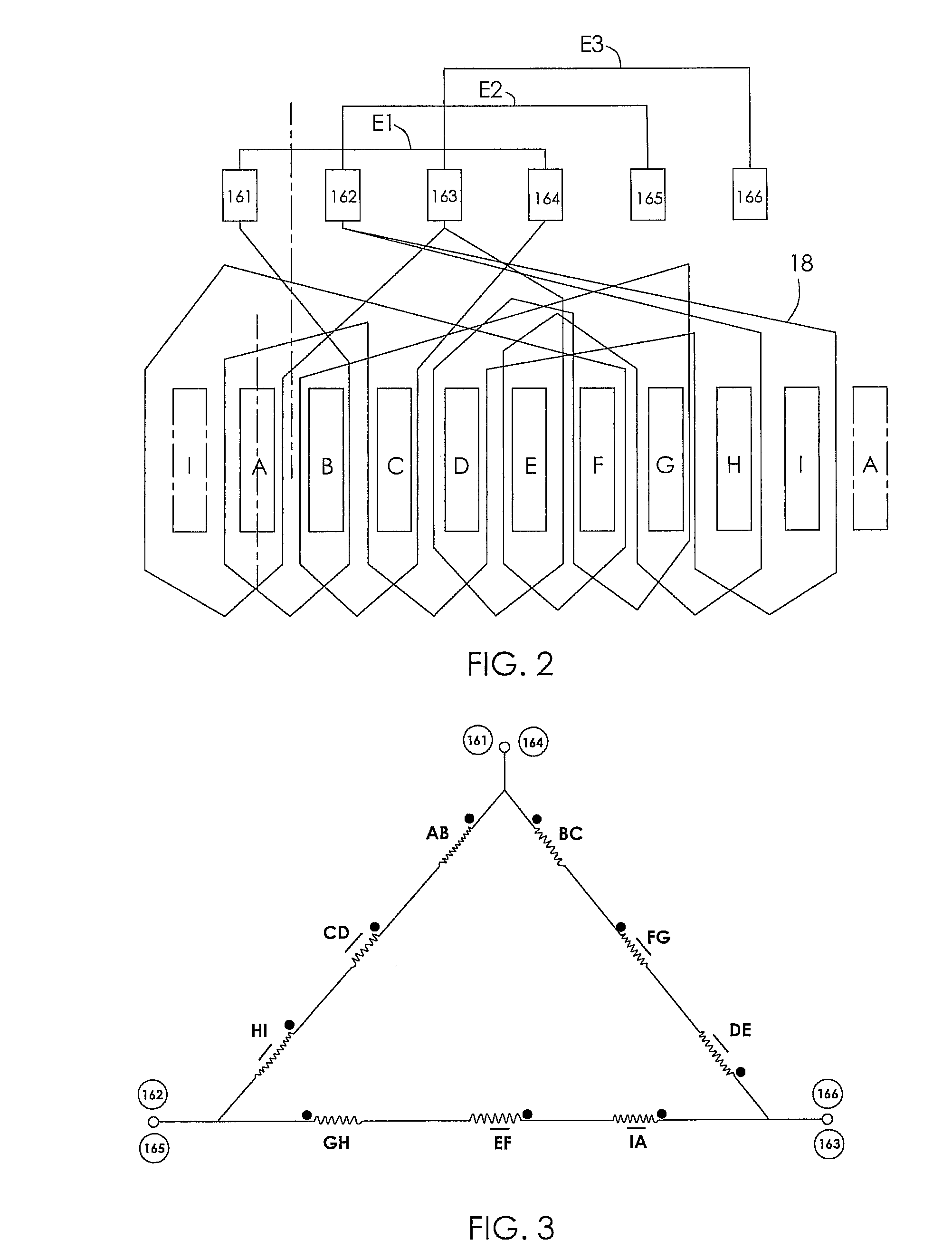
[0020]The rotor comprises a shaft 12, a rotor core 14 fixed on the shaft 12, and a commutator 16 fixed on the shaft 12 adjacent the rotor core 14. The rotor core 14 is formed by stacking laminations in the axial direction of the rotor. The rotor core 14 has n teeth A˜I and there are n rotor windings 18 wound about the teeth A˜I. A winding slot 142 is formed between adjacent teeth A˜I. The commutator 16 has m segments (also referred to as bars) 161˜166. The rotor windings 18 are wound in the winding slots 142 of the rotor core 14 and connected to the segments 161˜466 of the commutator 16. Preferably, m is an even number g...


PUM


Abstract

A permanent magnet electric motor includes a rotor and a stator magnetically coupled to the rotor. The rotor includes a shaft, a rotor core fixed to the shaft and having n teeth, n being an integer, a commutator fixed to the shaft adjacent the rotor core and having m segments, m being an even number less than n. Rotor windings are wound about the teeth and connected to the segments. The stator includes a plurality of permanent magnets surrounding the rotor core and brushes in sliding electrical contact with the commutator.

Description

CROSS REFERENCE TO RELATED APPLICATIONS[0001]This non-provisional patent application claims priority under 35 U.S.C. §119(a) from Patent Application No. 201010287466.6 filed in The People's Republic of China on Sep. 17, 2010.FIELD OF THE INVENTION[0002]This invention relates to an electric motor and in particular, to a small permanent magnet electric motor for use in an electric apparatus which requires a small and light motor.BACKGROUND OF THE INVENTION[0003]A typical permanent magnet direct current (PMDC) motor comprises a stator and a rotor rotatable relative to the stator. The stator comprises a housing and a plurality of permanent magnets fixed on the inner surface of the housing. The rotor comprises a shaft, a rotor core fixed to the shaft, a commutator fixed the shaft adjacent the rotor core. The rotor core comprises a plurality of teeth and slots formed between adjacent teeth. Windings are wound on the teeth of the rotor core and connected to segments of the commutator. The ...

Claims


Application Information

Patent Timeline
Patent Type & Authority Applications(United States)
IPC IPC(8): H01R39/04G02B7/04G02B7/02
CPCH02K3/28H02K23/32H02K23/26
Inventor LI, YUEJIANG, MAO XIONGZHAO, JIANLI, YONGHUA, HAI JUN
Owner JOHNSON ELECTRIC SA
Learn More