Virtual image formation method for an ultrasound device

a virtual image and ultrasound technology, applied in the field of virtual image formation of ultrasound devices, can solve the problems of unable to place a probe, delay in delivery of life-saving fluids or medications, and neither a simple nor risk-free procedur

Active Publication Date: 2012-03-22
SOMA RES LLC
View PDF7 Cites 114 Cited by
  • Summary
  • Abstract
  • Description
  • Claims
  • Application Information

AI Technical Summary

Benefits of technology

[0009]Also disclosed herein is an ultrasound device that can include an ultrasound transducer, a detector, and a processor. For instance, the detector can include an array of sensors. In one preferred embodiment, the sensors can be Hall effect transducers and the target that is associated with the probe for use with the device can be a magnet.

Problems solved by technology

This is neither a simple nor a risk-free procedure.
Risks of unsuccessful placement of a probe can range from minor complications, such as patient anxiety and discomfort due to repetition of the procedure following incorrect initial placement, to severe complications, such as pneumothorax, arterial or venous laceration, or delay of delivery of life-saving fluids or medications in an emergency situation.
Such techniques are very difficult perceptually.
For instance, these techniques are complicated by the fact that the person guiding the probe to the internal site is not the same person as is operating the ultrasound.
In addition, the generally thin, cylindrical probe is usually small and reflects very little of the ultrasound beam.
Moreover, as the cylindrical probe and the ultrasound beam are not generally normal to one another, the small amount of ultrasonic energy that is reflected from the probe will reflect at an angle to the incident beam, resulting in little if any of the reflected energy being detected by the ultrasound transducer.
As a result, the probe itself is difficult to visualize in the sonogram and the person placing the probe must attempt to guide the probe to the correct location using minimal visual feedback.
For example, the only visual feedback available is often only subtle artifacts of the motion of the probe such as slight changes in the sonogram as the probe deflects and penetrates the surrounding tissue.
Problems still exist with such devices however.
In addition, even if the probe passes for a length in line with the scanned plane, very little, if any, ultrasonic energy is reflected from the probe back to the transducer.
In fact, due to the lack of reflection off of the probe, visual cues to the location of the probe tip may be even more difficult to discern on a sonogram when using these devices.
In addition, in many of these devices, the probe passes through the ultrasound beam at a fixed depth range depending on the set angle of the probe guide, and this may not correspond to the depth of the desired subdermal site, in which case it may not be possible to show the juncture of the desired site and the probe tip on the sonogram at all.

Method used


Image

  • Virtual image formation method for an ultrasound device
  • Virtual image formation method for an ultrasound device
  • Virtual image formation method for an ultrasound device

Examples


example 1

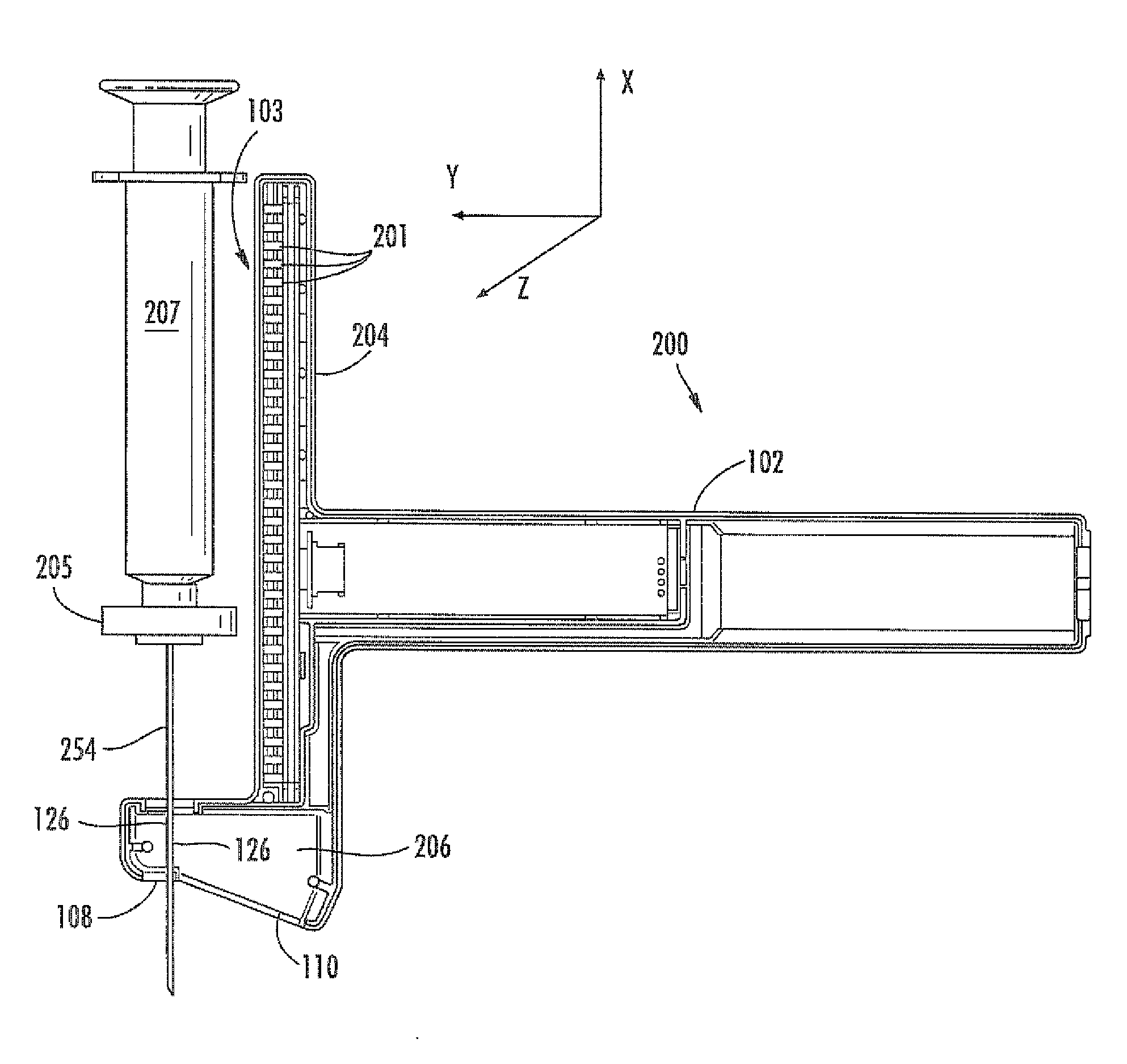
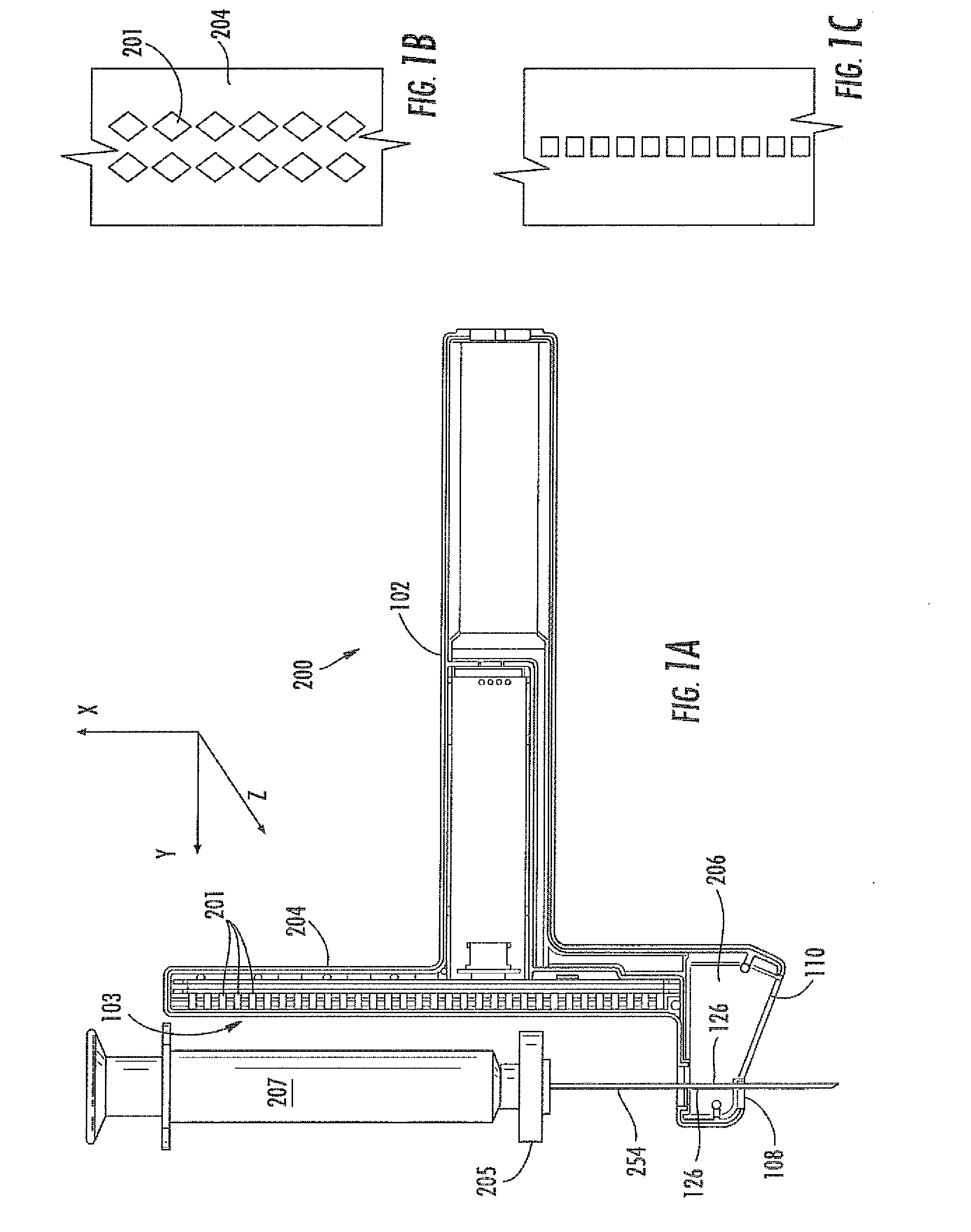
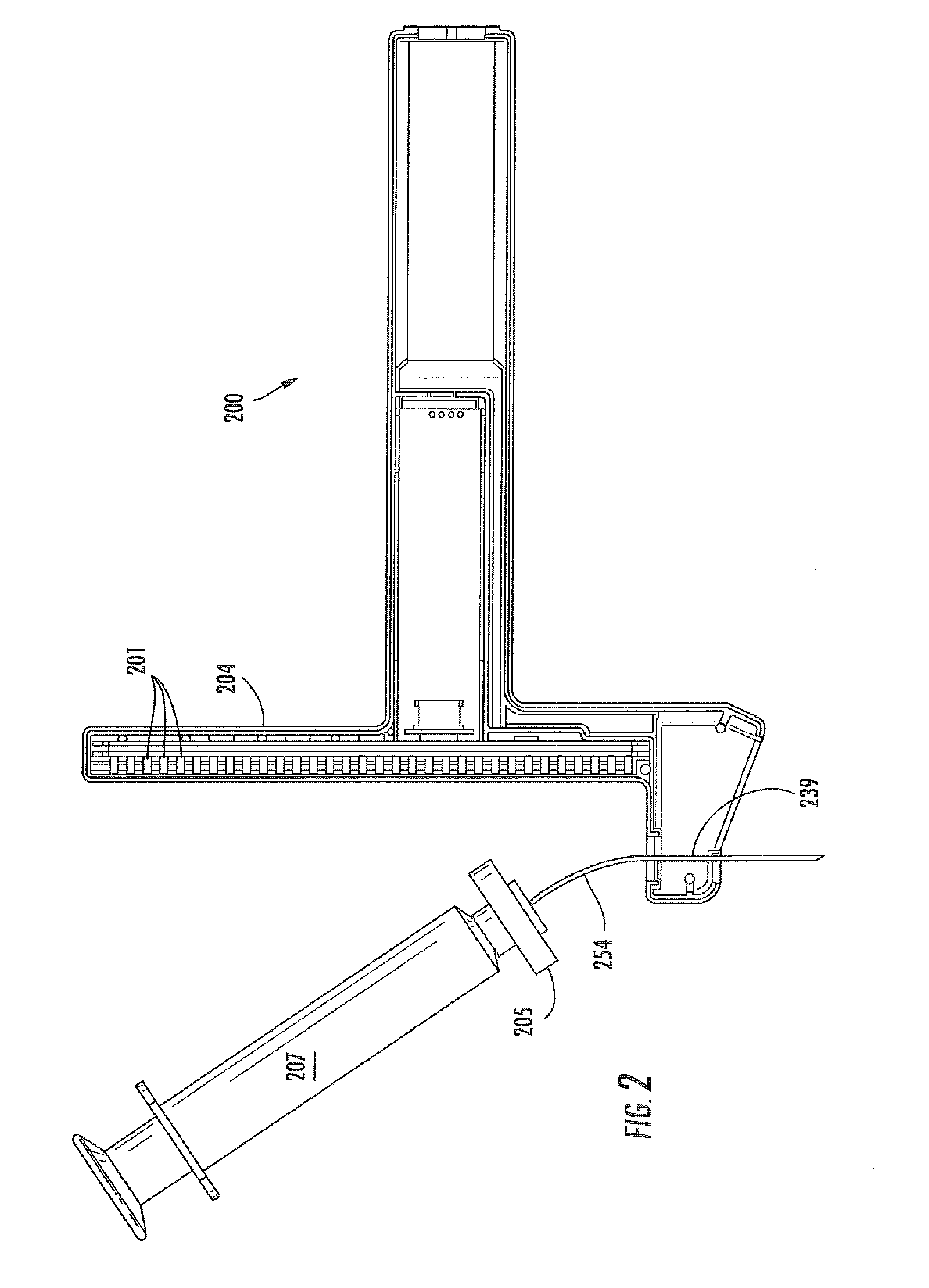
[0135]An ultrasound device as illustrated in FIG. 13 was utilized. The needle probe 254 was flexed away from the post 204 of the device, as shown. A sensor array 103 of Hall effect sensors was located within the post 204. The sensors used were ratiometric linear Hall effect sensors available from Allegro MicroSystems, Inc., model no. A1321. FIG. 13 also provides a top view 270 of the post 204, showing the curvature of the post to accommodate the target magnet 205. The needle 254 was flexed by increasing levels away from the post 204. Sensor array readings, SH, which can be converted to a location parameter by simple geometric conversion based upon the ultrasound device, are provided in the Table 1, below. Data in each row were obtained with the same fixed position of the needle.

TABLE 1Level H012345678910111213141516Meter702.5699696692689readings611608605602599596594SH520517514511509507506504502500499497496460458455453451449447446444443442441440439437401399397394393391389386384383381...

example 2

[0143]FIG. 14 illustrates a geometric model utilized to describe the tilt of a target magnet with the flexing of an attached probe from alignment with a probe guide. An assumption was made that the needle was bent with a constant radius of R. (In this example, the value for the level index, H, has been converted to the distance from the sensor array to the magnet.) The following equations can be written:

LB=R*α

h=2R*sin2(α / 2)

h+RM=H+RM*cos(α)

[0144]RM is the magnet radius (11 mm in this example).

[0145]Thus,

H=[LB*sin2(α / 2)] / α−RM*cos(α)

[0146]This equation was solved digitally, and the results for the values of α (in radians) are shown in Table 2, below.

TABLE 2LB =LB =H (mm)LB = 68 mmLB = 58 mmLB = 48 mm38 mm28 mm0000003.53.343.94.685.847.765.56.67.79.2211.4414.927.59.8411.4413.6416.7821.649.513.0415.1417.9621.962811.516.218.7622.227.0213.519.3422.3426.38

[0147]The results of Examples 1 and 2 were combined to provide a graph (FIG. 15) illustrating the experimentally obtained values for the ...

example 3

[0148]A second set of data for SH, the output of the Hall effect sensor array, were obtained utilizing a system similar to that described above in Example 1. Raw data is provided below in Table 3. Best fit of the data provided values of the correlation factors a=−0.051 and b=4.26. Thus, the correlation equations are as follows (the values for Soffs and SH are in units of 0.1 mm, hence the conversion factor in the equation):

LB=(Soffs−SH) / 10−LC,

S0=SH+(4.26−0.051*LB)*H,

TABLE 3LB =LB =H (mm)LB = 68 mmLB = 58 mmLB = 48 mm38 mm28 mm0203306404501597.53.51992963974935885.5196293.53844865817.5194289.53804745659.5192285.537647055811.5189281.537346413.5184276.5371

[0149]Utilizing these correlation factors in the processing software, a test was run. A needle of length 88.9 mm (3.5 inches) was used. A value of Soffs was determined to be 685. A value of LC was determined to be 20.9 mm.

[0150]A device as illustrated in FIG. 13 including a detector was used. The detector provided the following readi...


PUM


Abstract

Disclosed are ultrasound devices and methods for use in guiding a subdermal probe during a medical procedure. A device can be utilized to guide a probe through the probe guide to a subdermal site. In addition, a device can include a detector in communication with a processor. The detector can recognize the location of a target associated with the probe. The processor can utilize the data from the detector and create an image of a virtual probe that can accurately portray the location of the actual probe on a sonogram of a subdermal area. In addition, disclosed systems can include a set of correlation factors in the processor instructions. As such, the virtual probe image can be correlated with the location of the actual probe.

Description

BACKGROUND OF THE INVENTION[0001]Medical probe devices are utilized for many purposes, chief of which include catheterization, centesis, and biopsy procedures. Percutaneous placement of probes using these devices is often performed with techniques which rely on ascertaining the correct locations of palpable or visible structures. This is neither a simple nor a risk-free procedure. For instance, proper insertion and placement of a subdermal probe depends on correct localization of anatomical landmarks, proper positioning of the patient in relation to the care provider, and awareness of both the depth of the subdermal location and angle from the point of probe insertion. Risks of unsuccessful placement of a probe can range from minor complications, such as patient anxiety and discomfort due to repetition of the procedure following incorrect initial placement, to severe complications, such as pneumothorax, arterial or venous laceration, or delay of delivery of life-saving fluids or med...

Claims


Application Information

Patent Timeline
Patent Type & Authority Applications(United States)
IPC IPC(8): A61B8/14
CPCA61B8/0841A61B8/4411A61B8/4422A61B8/4455A61B2019/5276A61B2017/3407A61B2019/462A61B2019/4857A61B2019/5251A61B17/3403A61B2090/062A61B2090/0811A61B2034/2051A61B2090/378A61B5/062A61B8/4483A61B8/461A61B2017/3413
Inventor HAGY, M. DEXTERPETROV, ANDREWBURRESON, BERNARD JAMESDOUDKIN, ANDRE
Owner SOMA RES LLC
Why Eureka
Try Eureka