Solar thermal concentrator apparatus, system, and method

Inactive Publication Date: 2012-03-29
WINSTON CONE OPTICS
View PDF2 Cites 29 Cited by
  • Summary
  • Abstract
  • Description
  • Claims
  • Application Information

AI Technical Summary

Benefits of technology

[0007]The inventor has realized that a concentrator assembly may be used, e.g., to collect solar energy to produce heat. Embodiments of the concentrator assembly feature a wide acceptance angle, allowing for use

Problems solved by technology

Tracking, however, is technically demanding because solar collectors are commonly fairly larg

Method used


Image

  • Solar thermal concentrator apparatus, system, and method
  • Solar thermal concentrator apparatus, system, and method
  • Solar thermal concentrator apparatus, system, and method

Examples


Embodiment Construction

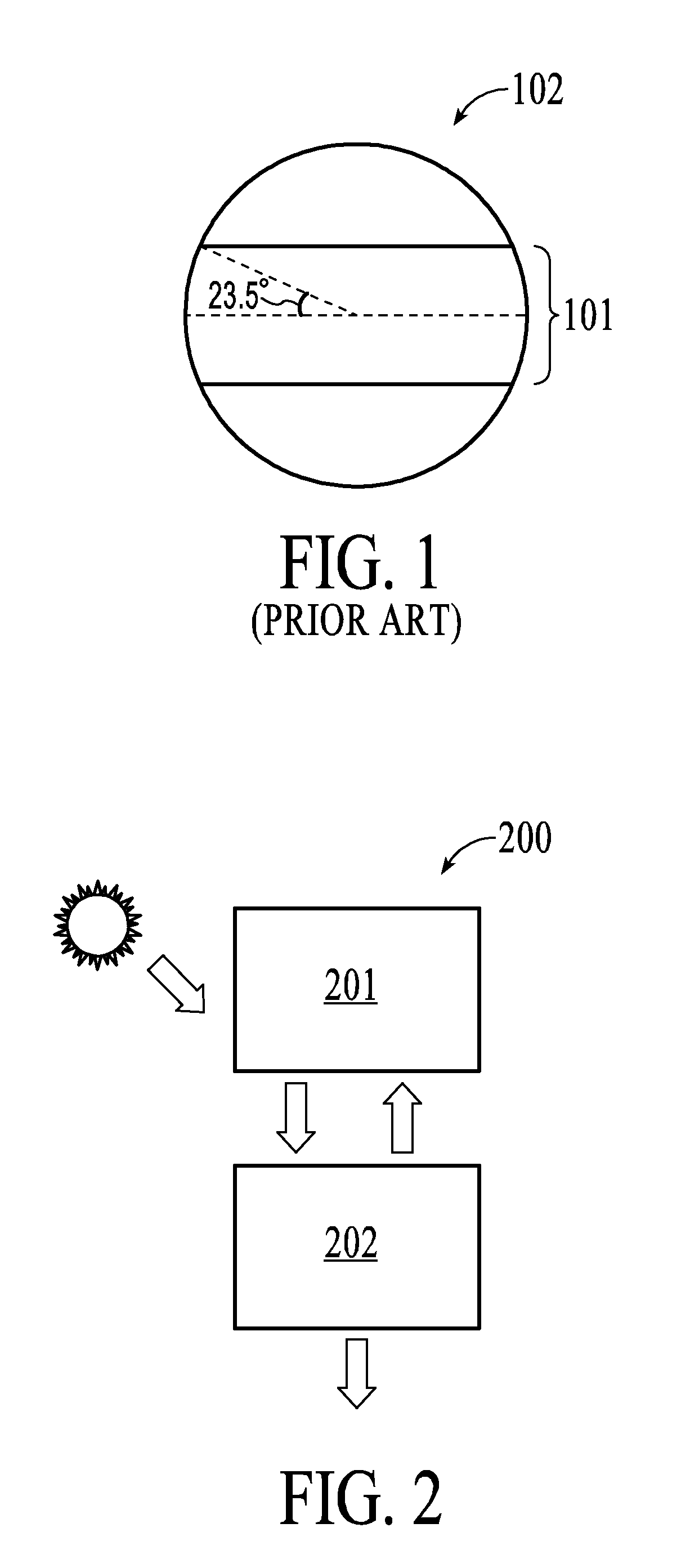
[0080]From a thermodynamic viewpoint, the solar geometry may be described in direction cosines, which are the momenta of the light rays. Referring to FIG. 1, the sun over the year occupies a band 101 inside a unit radius circle 102 which is ±sin 23.5 deg. This band is nearly ½ the area of the circle, from which follows, e.g. as described in detail U.S. Pat. No. 6,467,916 to Roland Winston (incorporated herein by reference in its entirety), that the maximum theoretical concentration for a trough shaped concentrating reflector using no seasonal adjustments is very close to 2.

[0081]In some embodiments, this limit may be increased. In cases where the target (absorber) is immersed in a refractive material having an index of refraction (n), this limit is multiplied by n squared because the momentum of a light ray is actually the index of refraction x direction cosine. For example, for n˜1.5 (typical of glass or PMMA) and restricting the absorber irradiance to 60 deg., the maximum concentr...


PUM

PropertyMeasurementUnit
Fractionaaaaaaaaaa
Angleaaaaaaaaaa
Angleaaaaaaaaaa

Abstract

An apparatus is disclosed including: a trough shaped reflector extending along a longitudinal axis and including at least one reflective surface having a shape which substantially corresponds to an edge ray involute of the absorber.

Description

CROSS REFERENCE TO RELATED PATENT APPLICATIONS[0001]The instant patent application claims priority to U.S. Provisional Patent Application No.: 61385890 to Roland Winston filed on Sep. 23, 2010, which is herein incorporated by reference in its entirety.STATEMENT OF RIGHTS UNDER THE INVENTION[0002]This invention was made with government support. The invention was made with the State of California's support under the California Energy Commission contract No. 5005-05-21. The Energy Commission has certain rights to this invention.BACKGROUND OF THE INVENTION[0003]This disclosure relates to devices for the transmission of radiation, especially of light. In particular, it is related to a non-focusing reflector for the concentration of radiation such as sunlight at a desired region over a wide range of angles of incidence.[0004]A number of systems for passive or non-tracking reflecting concentration of solar energy have been produced in the past. Among such systems are those shown in U.S. Pa...

Claims


Application Information

Patent Timeline
IPC IPC(8): F24J2/05F24J2/24B21D53/02F24J2/12F24S10/30F24S10/40F24S10/70F24S10/95F24S23/71
CPCB21D53/02F24J2/05F24J2/12Y10T29/49355Y02E10/44Y02E10/42F24J2/24F24S23/80F24S23/74F24S10/75F24S10/25F24S10/40F24S10/45F24S10/70F24S10/30F24S2010/71Y02B10/20Y02E10/40
Inventor WINSTON, ROLAND
Owner WINSTON CONE OPTICS
Why Eureka
Try Eureka