Subterranean Cutting Tool Structure Tailored to Intended Use

a cutting tool and subterranean technology, applied in earthwork drilling, construction, well accessories, etc., can solve the problems of affecting the use of the tool, the center of the mill is very low relative speed to the surface being cut, and the demand for different locations of the mill is not symmetrical, etc., to achieve high impact resistance, good temperature bonding strength, and high wear resistance

Active Publication Date: 2012-03-29
BAKER HUGHES INC
View PDF6 Cites 15 Cited by
  • Summary
  • Abstract
  • Description
  • Claims
  • Application Information

AI Technical Summary

Benefits of technology

[0009]A mill cutting structure is differently configured in three zones. Those zones are the center, the outer edge and in between. At the center has highly wear resistant material that has good temperature bond strength and high impact resistance. The outer periphery can have a material that is highly resistant to wear and impact. In between can be inserts such as used in the Metal Muncher® mills using sintered carbide shapes that resist tracking and create a chipping rather than a grinding action. The shapes should have high edge retention capability and shapes such as a double sided pyramid can be used. The wear patterns of prior designs are addressed to allow longer and faster milling of the fish.

Problems solved by technology

While there was some intuitive rationale behind symmetry, the demands on different locations of a mill are not symmetrical and in certain cutting applications the limitations of such prior designs were made apparent.
The center of the mill has very low relative speed to the surface being cut and is a region where there is high abrasion and heat generation.
In the previous designs this region tended to core badly as the matrix softened from heat and abrasion and then sloughed off to create the coring effect.
As the core formed the cutting around the middle of the mill body deteriorated and as a result of that the ability of the mill to advance into the fish being milled was also impeded.
When chunks of the packer break off such as broken pieces of slips and the circulating fluid has to carry the cuttings to the edge of the body and then up the sides through recesses or water courses so that the cuttings can be recovered at the surface what results is high impact loading at the transition between the bottom and side of the mill such that the edge gets rounded off.
This removal of the cutting structure from the periphery impedes the cutting ability of the mill.
This effect can also require a trip in the hole for mill replacement which, particularly in offshore locations, can be a very expensive proposition.

Method used


Image

  • Subterranean Cutting Tool Structure Tailored to Intended Use
  • Subterranean Cutting Tool Structure Tailored to Intended Use
  • Subterranean Cutting Tool Structure Tailored to Intended Use

Examples


Embodiment Construction

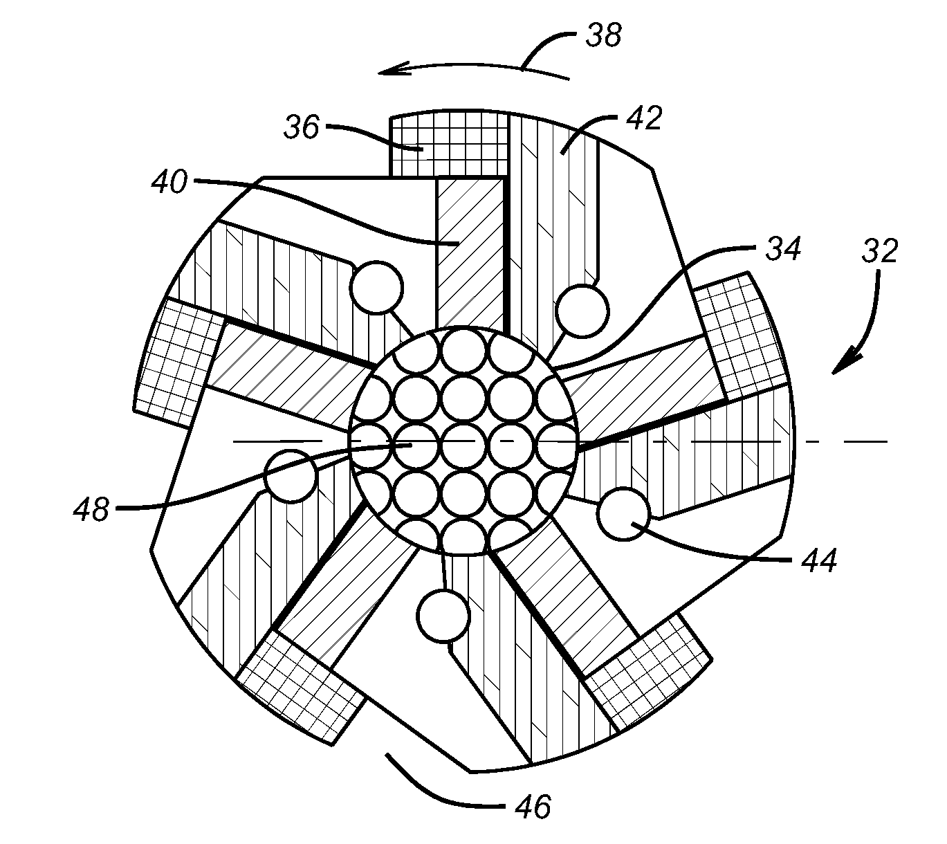
[0019]FIG. 6 shows the bottom view of a mill 32 that has a central zone 34 and a plurality of leading peripheral spaced apart zones 36 as determined by the direction of rotation represented by the arrow 38. In between are leading 40 and trailing 42 cutting regions where most of the cutting takes place and the chips off the fish are formed. The trailing region is also disposed behind the peripheral zones 36 in the direction of rotation. A series of ports 44 border the trailing region 42 and are there to allow pumped fluid to drive the cuttings to the edges where they can make a turn uphole through gaps such as 46. The cutting elements 48 in zone 34 are illustrated in detail in FIG. 7. This shape is formed from a starting shape of a sphere and cut with a cylindrical drill that passes through the shape at four perpendicular orientations. This leaves end rounded shapes 50 and 52 that are spherical and are separated by four part cylindrical walls of which three are visible in FIG. 7 name...


PUM

PropertyMeasurementUnit
insert anglesaaaaaaaaaa
angleaaaaaaaaaa
anglesaaaaaaaaaa

Abstract

A mill cutting structure is differently configured in three zones. Those zones are the center, the outer edge and in between. At the center has highly wear resistant material that has good temperature bond strength and high impact resistance. The outer periphery can have a material that is highly resistant to wear and impact. In between can be inserts such as used in the Metal Muncher® mills using sintered carbide shapes that resist tracking and create a chipping rather than a grinding action. The shapes should have high edge retention capability and shapes such as a double sided pyramid can be used. The wear patterns of prior designs are addressed to allow longer and faster milling of the fish.

Description

FIELD OF THE INVENTION[0001]The field of the invention is subterranean milling tools and more particularly those mills that employ discrete cutting structures at different locations on the mill body to address the expected type of wear unique to that location so that overall milling effectiveness is improved.BACKGROUND OF THE INVENTION[0002]There are occasions where downhole devices such as packers or bridge plugs or cement shoes are milled out. Other times there is a tubing string or portion of a tubing string that needs to be cut so that subsequent operations can continue. Over time the design of such mills has evolved to address the need for greater speed and cutting efficiency. In the 1980s Baker Hughes came out with a line of mills known as Metal Muncher® as illustrated in U.S. Pat. Nos. 5,038,859 or 5,086,838; 4,796,709 and 5,456,312.[0003]One example of this design is shown in FIGS. 1 and 2. The typical mill of this type had a body 10 with a central flow passage 12 that lead ...

Claims


Application Information

Patent Timeline
Patent Type & Authority Applications(United States)
IPC IPC(8): E21B10/36
CPCE21B29/00E21B10/43E21B29/002
Inventor LYNDE, GERALD D.
Owner BAKER HUGHES INC
Why Eureka
Try Eureka