Sine wave spring
- Summary
- Abstract
- Description
- Claims
- Application Information
AI Technical Summary
Benefits of technology
Problems solved by technology
Method used
Image
Examples
Embodiment Construction
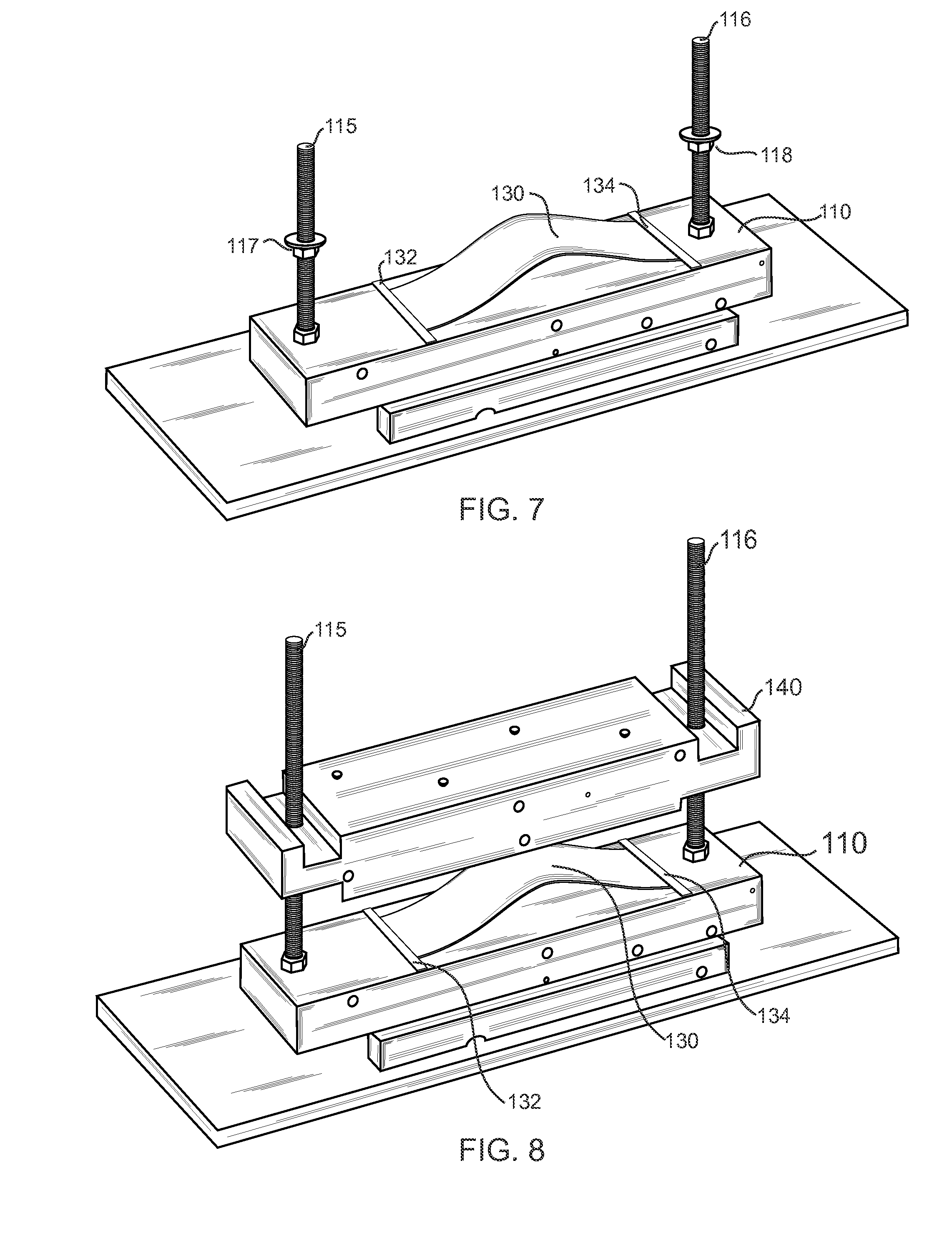
[0058]FIGS. 7-15 illustrate how the spring of the present invention works, as installed on a test bed device for the purposes of illustration. FIG. 7 is a perspective view of the test cell used in the present invention to demonstrate the operation of the sine wave spring 130, illustrating the spring material 130 placed on the bed portion or platen 110. The spring 130, as noted previously, could be made of a Mylar material, spring steel, 2024-T3 aluminum, and epoxy impregnated carbon fiber, or other flexible materials. Stops 132, 134 are provided at each end of the spring material 130 on platen 110 to hold the sheet 130 in place on the platen 130. Note that the spring material 130 lays flat at the end portions near the stops 132, 134 on the platen 130. FIG. 9 is a front view of the test cell used in the present invention to demonstrate the operation of the sine wave spring 130, illustrating the spring material 130 placed on the platen 110.
[0059]FIG. 8 is a perspective view of the tes...
PUM
 Abstract
Description
Claims
Application Information
 - R&D
- Intellectual Property
- Life Sciences
- Materials
- Tech Scout
- Unparalleled Data Quality
- Higher Quality Content
- 60% Fewer Hallucinations
Browse by: Latest US Patents, China's latest patents, Technical Efficacy Thesaurus, Application Domain, Technology Topic, Popular Technical Reports.
© 2025 PatSnap. All rights reserved.Legal|Privacy policy|Modern Slavery Act Transparency Statement|Sitemap|About US| Contact US: help@patsnap.com


