Variable amplitude sine wave spring

Inactive Publication Date: 2012-05-24
GUTHRIE WALKER LEE
View PDF2 Cites 26 Cited by
  • Summary
  • Abstract
  • Description
  • Claims
  • Application Information

AI Technical Summary

Benefits of technology

[0023]The present inventor also noted that the force needed to maintain the compressed spring in each of the new phases was considerably less than the threshold force needed to form it. This energy absorbing effect is key to the self-dampening nature of the spring. This effect prevents the undesirable recoil of undampened spring systems. Some crash attenuation barriers, for ex

Problems solved by technology

However, the apparatus of the Prior Art utilized the sine wave construction and the comp

Method used


Image

  • Variable amplitude sine wave spring
  • Variable amplitude sine wave spring
  • Variable amplitude sine wave spring

Examples


Embodiment Construction

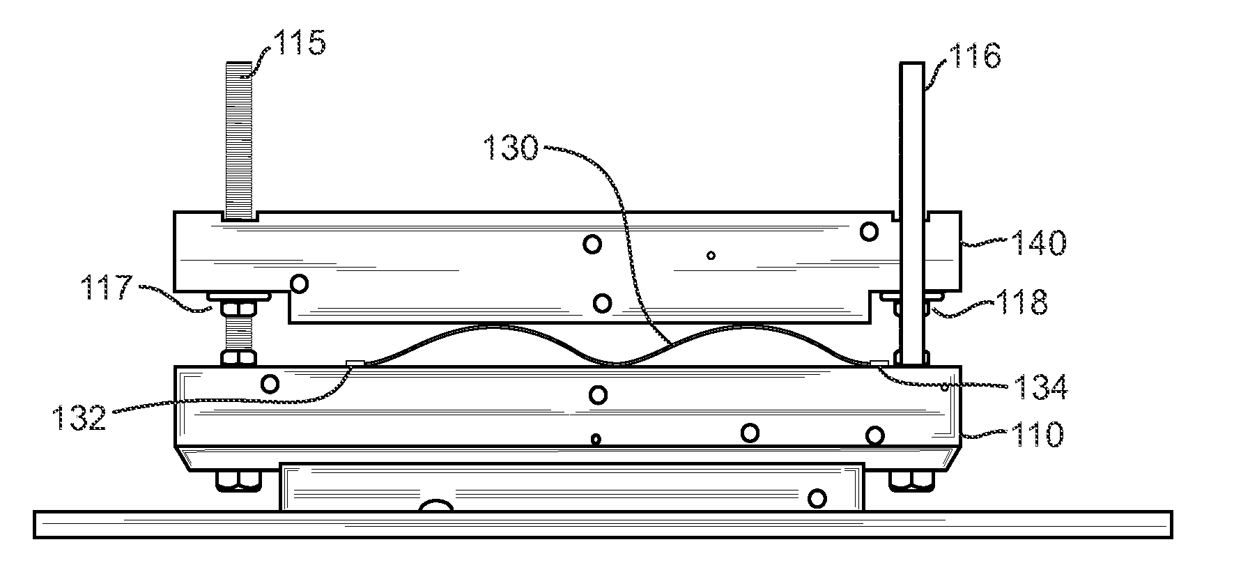
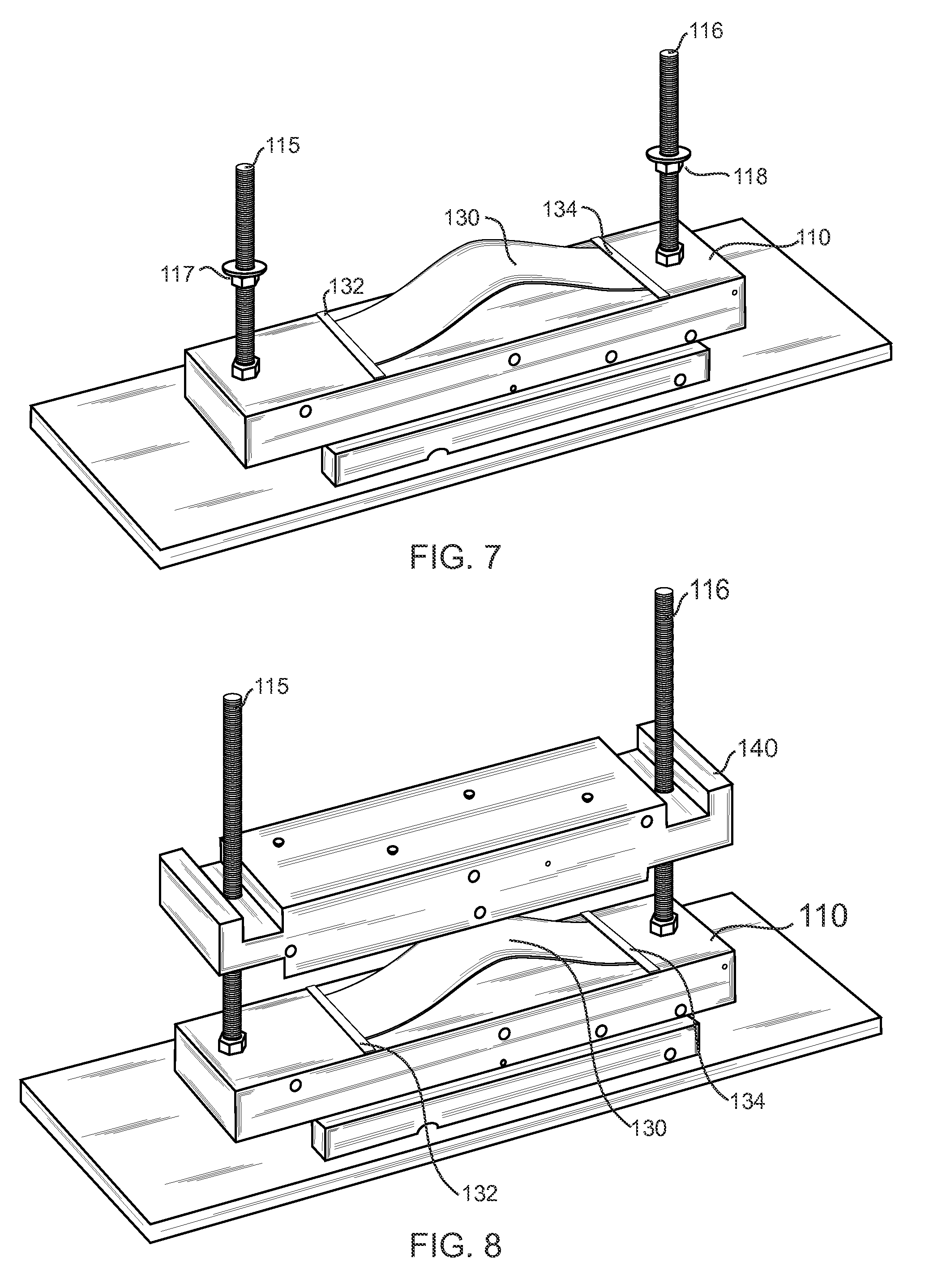
[0070]FIGS. 7-15 illustrate how the spring of the present invention works, as installed on a test bed device for the purposes of illustration. FIG. 7 is a perspective view of the test cell used in the present invention to demonstrate the operation of the sine wave spring 130, illustrating the spring material 130 placed on the bed portion or platen 110. The spring 130, as noted previously, could be made of a Mylar material, spring steel, 2024-T3 aluminum, and epoxy impregnated carbon fiber, or other flexible materials. Stops 132, 134 are provided at each end of the spring material 130 on platen 110 to hold the sheet 130 in place on the platen 130. Note that the spring material 130 lays flat at the end portions near the stops 132, 134 on the platen 130. FIG. 9 is a front view of the test cell used in the present invention to demonstrate the operation of the sine wave spring 130, illustrating the spring material 130 placed on the platen 110.

[0071]FIG. 8 is a perspective view of the tes...


PUM


Abstract

A spring is formed of a relatively thin sheet of spring material, which is constricted and held in place at each end forming a bell curve being located between two substantially planar members. As additional compressive force is applied in the vertical direction, the curve then compresses and starts to form sine waves. In an improved embodiment of the present invention, the sine wave spring is formed in a wedge shape, so that it is gradually taller and more progressive. This embodiment has been tested for use as a trailer spring with positive results. This wedge-shaped sine wave spring provides even more advantages over the Prior Art. The wedge-shaped prototype illustrates also how the present invention may be expanded to other shapes, in order to alter the spring characteristics, and also for packaging and other concerns.

Description

CROSS-REFERENCE TO RELATED APPLICATIONS[0001]The present application is a Continuation-In-Part of U.S. patent application Ser. No. 13 / 021,867, filed Feb. 7, 2011, which in turn claims priority from Provisional U.S. Patent Application No. 61 / 387,546 filed on Sep. 29, 2010, both applications are incorporated herein by reference.FIELD OF THE INVENTION[0002]The present invention relates to springs. In particular, the present invention is directed toward a spring made from a flat plate material, forced into a sine wave shape.BACKGROUND OF THE INVENTION[0003]Guthrie, U.S. Pat. No. 4,708,757, issued Nov. 24, 1987 to the same inventor as the present application, discloses a method of forming a corrugated panel. In the Guthrie '757 patent, a corrugated panel in which at least the central corrugated sheet is formed from an elastically deformable material such as polyethylene synthetic plastic or spring steel is disposed and secured between a pair of cover sheets. The method of forming the pan...

Claims


Application Information

Patent Timeline
IPC IPC(8): G01G3/00F16F3/02F16F7/00F41A25/10B60R19/02B60N2/54F16L3/00F16F1/18B60G11/02
CPCB60G11/00G01G19/44B60N2/24B60N2/4242B60N2/42709B60N2/54B60R19/18B60R2019/1866F16F1/185F16F3/023F16L3/20F16L55/035F41C23/08G01G3/08G01L1/00G01G19/02G01G19/08B60G2202/00
Inventor GUTHRIE, WALKER LEE
Owner GUTHRIE WALKER LEE
Why Eureka
Try Eureka