Sectionalized Electromechanical Machines Having Low Torque Ripple and Low Cogging Torque Characteristics

a technology of electromechanical machines and torque ripple, which is applied in the field of electromechanical machines, can solve the problems of increased cost, increased cost, increased increased so as to reduce torque ripple and cogging torque

Inactive Publication Date: 2012-03-29
WEG ELECTRIC CORP
View PDF7 Cites 54 Cited by
  • Summary
  • Abstract
  • Description
  • Claims
  • Application Information

AI Technical Summary

Benefits of technology

[0008]In still another implementation, the present disclosure is directed to a method for reducing torque ripple and cogging torque in an electromechanical machine having rotor poles and stator poles disposed on relatively rotating structures that cooperate to generate electricity from rotation or convert electricity to. The method includes: conceptually dividing at least one of the relatively rotating structures into a plurality of sections to provide a sectionalized structure with each section having ends adjacent a next section; arranging the poles of the sectionalized structure in a plurality of sets of poles, each set disposed within one the section and having two end poles, one at each section end; and positioning adjacent poles within each set of poles as a function of the frequency of the torque ripple harmonic to be reduced.

Problems solved by technology

However, segmented designs to date have had a variety of drawbacks such as increased expense due to more difficult manufacture and maintenance, greater possibility of damage to coils, lost torque, and / or increase in torque ripple and cogging torque.
While this design can be less expensive than more complex winding patterns, it can suffer from even more significant negative effects due to cogging torque and torque ripple.
To address these problems, various tooth skewing schemes have been developed but these again raise cost of the design and can be incompatible with segmented designs due to the difficulty of assembly.

Method used


Image

  • Sectionalized Electromechanical Machines Having Low Torque Ripple and Low Cogging Torque Characteristics
  • Sectionalized Electromechanical Machines Having Low Torque Ripple and Low Cogging Torque Characteristics
  • Sectionalized Electromechanical Machines Having Low Torque Ripple and Low Cogging Torque Characteristics

Examples


Embodiment Construction

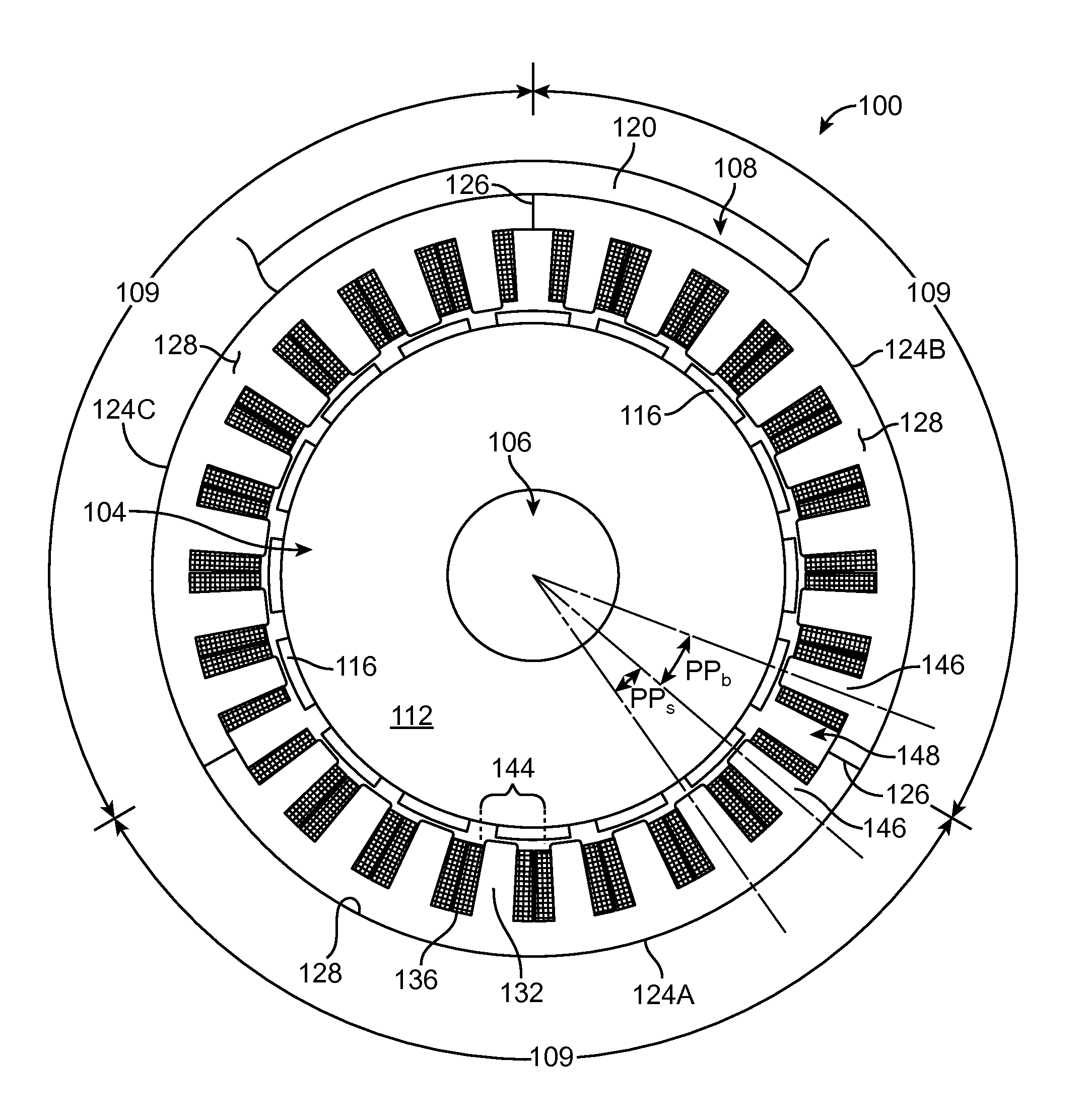
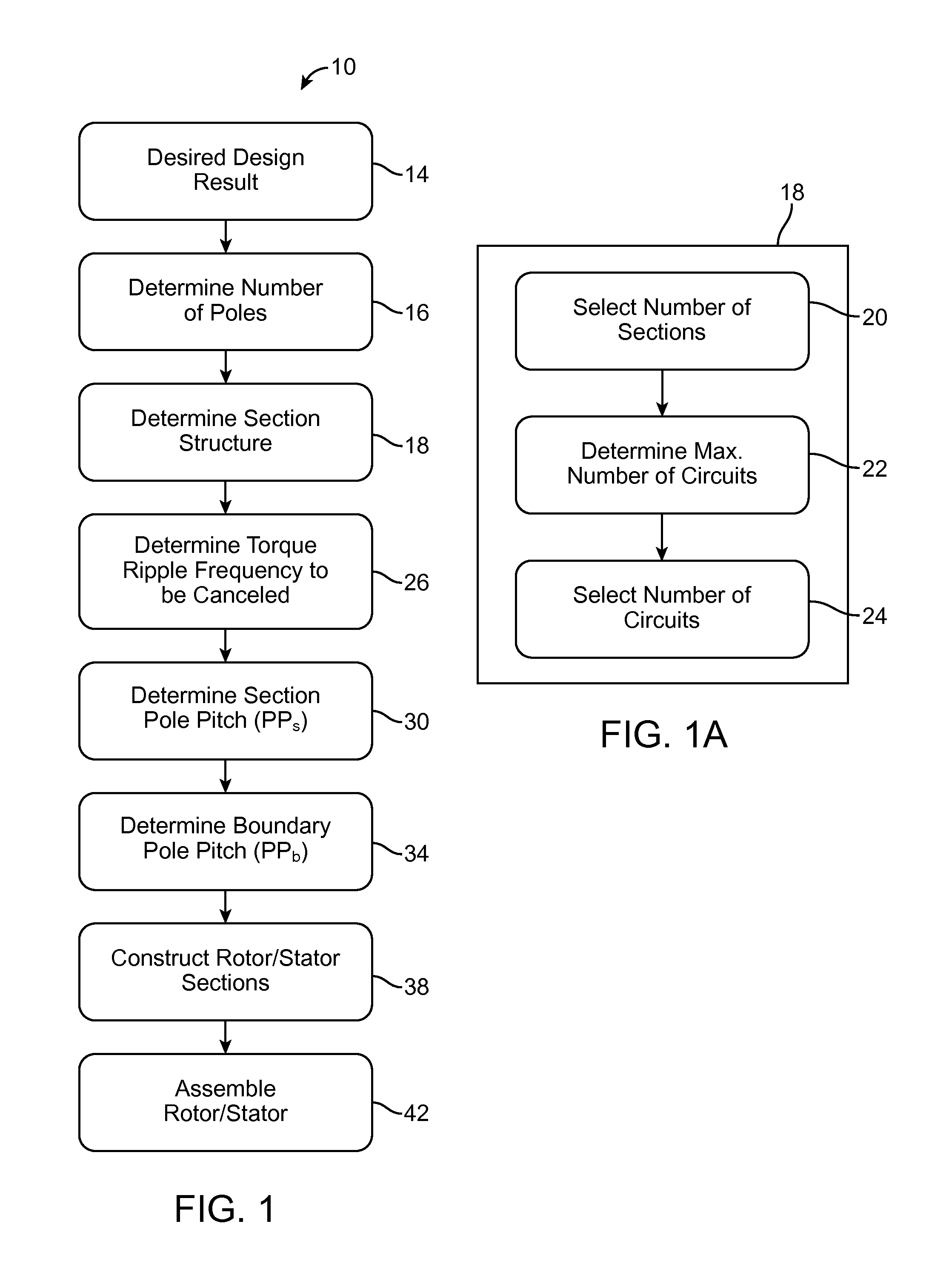
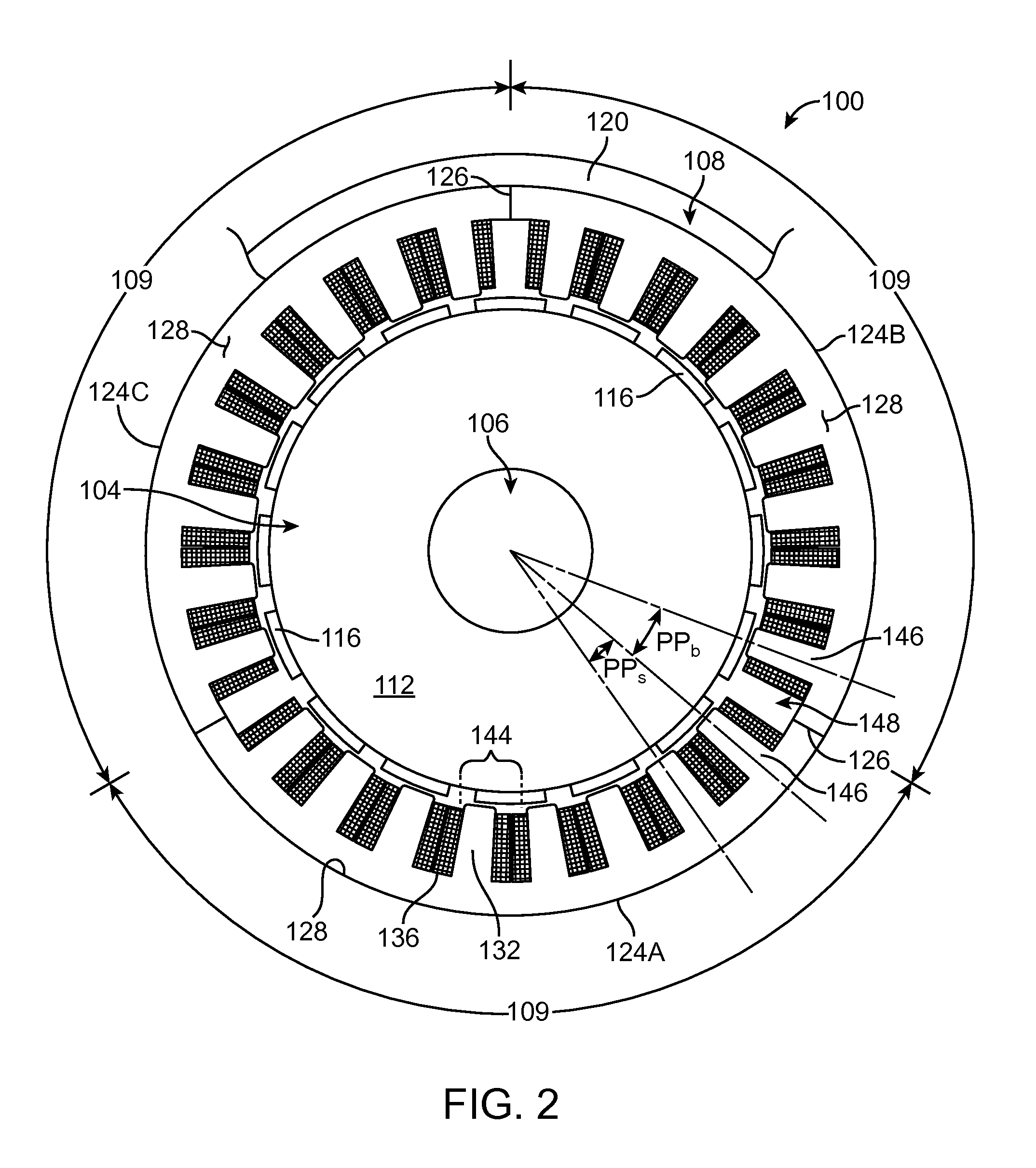
[0018]An electromechanical machine as referred to herein is a machine for the generation of electrical energy from mechanical work, e.g., producing electricity from the rotation of turbine blades, or the conversion of electrical energy to mechanical work, e.g., the use of electricity to rotate an object. Generally, the present disclosure is directed to an apparatus and method including sectionalized stator and rotor designs, and for reducing cogging torque and torque ripple in an electromechanical machine. Embodiments of the invention have particular application to single tooth concentric wound devices, although it may be applicable to other designs as well.

[0019]The terms sectionalizing and segmenting are used in many ways in the art with respect to electromechanical machines. For example, they can refer to constructing a rotor or stator of a machine in a plurality of arched or curved sections that can be installed into a structural frame to create a stator or rotor. Sectionalizing...


PUM

PropertyMeasurementUnit
electricalaaaaaaaaaa
frequencyaaaaaaaaaa
Phaaaaaaaaaa

Abstract

A method and apparatus for reducing or eliminating the effects of torque ripple and cogging torque and otherwise improving performance in an electromechanical machine such as a motor or generator. The rotor and/or stator is conceptually sectionalized and the sections spaced apart by amount sufficient to alleviate deleterious aspects of cogging torque and torque ripple. Positioning of the stator teeth or rotor magnets is determined based on the calculated spacing. Conceptual sections may be formed as physically individual segments. Unwound teeth may be disposed in end spaces between sections occupying less than the entire area of the end space.

Description

RELATED APPLICATION DATA[0001]This application claims the benefit of priority of U.S. Provisional Patent Application Ser. No. 61 / 385,660, filed on Sep. 23, 2010, and titled “Sectionalized Electromechanical Machines Having Low Torque Ripple and Low Cogging Torque Characteristics,” which is incorporated by reference herein in its entirety.FIELD OF THE INVENTION[0002]The present invention generally relates to the field of electromechanical machines. In particular, the present invention is directed to a sectionalized electromechanical machine having low torque ripple and low cogging torque characteristics.BACKGROUND[0003]Electromechanical machines, i.e., generators or motors, may be designed and configured in a wide variety of sizes—from, for example, relatively small diameter servomotors and automobile alternators to relatively large diameter hydroelectric turbines and powerful electric motors for ship propulsion or other uses. Given the size of some of these machines, there has been i...

Claims


Application Information

Patent Timeline
Patent Type & Authority Applications(United States)
IPC IPC(8): H02K1/12H02K15/02H02K1/22
CPCH02K1/148H02K1/278H02K21/16Y10T29/49012H02K2213/03H02K2213/12Y02E10/725H02K29/03Y10T29/49009Y02E10/72H02K1/165H02K15/026
Inventor PETTER, JEFFREY K.HURTADO, HECTOR
Owner WEG ELECTRIC CORP
Why Eureka
Try Eureka