Differential sand compaction sensor

a technology of sand compaction and sensor, which is applied in the direction of resistance/reaction/impedence, instruments, measurement devices, etc., can solve the problems of affecting the resulting mold properties, affecting the effectiveness of monitoring compaction, and mold may develop cracks or even collapse, etc., to achieve more effective compaction, reduce changes due to the properties of sand, and monitor the effect of compaction

Active Publication Date: 2012-03-29
TENNESSEE TECHNOLOGICAL UNIVERSITY
View PDF2 Cites 3 Cited by
  • Summary
  • Abstract
  • Description
  • Claims
  • Application Information

AI Technical Summary

Benefits of technology

[0010]A microcontroller or microprocessor (such as in a computing device) is used to acquire the voltage signal and display the voltage signal corresponding to each chamber. The microcontroller or microprocessor is also used to implement an algorithm based on the differential measurements of the compaction in each of said compaction chambers. One of the simplest algorithms that can be implemented to monitor compaction effectiveness is to obtain the ratio of changes in compaction of the upper and lower chambers. This ratio will always be less than or equal to unity and a higher ratio shows a more effective compaction. Changes due to the properties of the sand are reduced by using the ratio of the capacitance measurement from the two chambers, where the dielectric constant of the sand in the two chambers is almost identical. The design of the lower chamber to fill and compact easily makes sure that this chamber provides an indicator of best possible compaction, under a given set of conditions, to use as a reference.

Problems solved by technology

Greensand characteristics are normally measured from the muller, and are limited to information on the greensand at that time.
Any of these processes can affect the resulting mold properties.
In addition, after the greensand mold is made, it is moved to the pour station, and during this movement, the mold may develop cracks or may even collapse.
Problems with a mold usually cannot be detected by visual inspection.

Method used


Image

  • Differential sand compaction sensor
  • Differential sand compaction sensor

Examples


Embodiment Construction

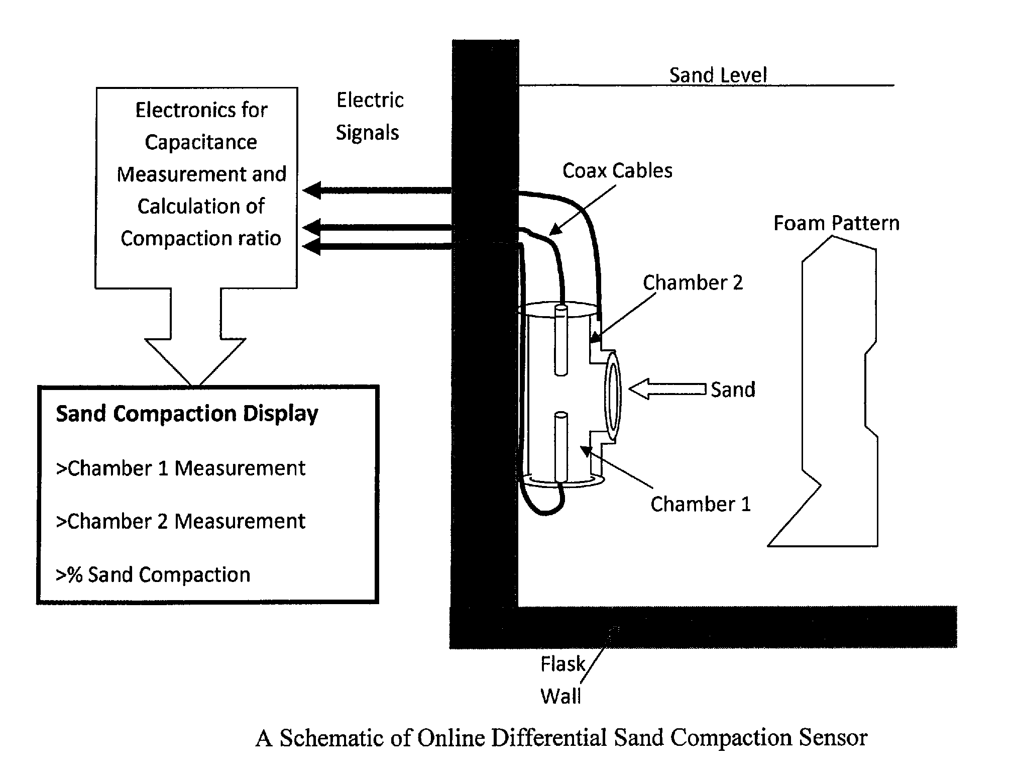
[0013]In one exemplary embodiment, the present invention comprises one or more sensors used to monitor the effectiveness of sand compaction on a production line (i.e., “online”). The sensor's response measures the changes in sand compaction, which is affected by the mechanics of the vibration system such as motor and linkage wear, changes in the sand properties such as fine content and loss on ignition percentage, and environmental changes such as temperature and humidity.

[0014]In one embodiment, a sensor comprises multiple chambers where the sand is compacted, with each of these chambers having a different difficulty in resisting sand filling and compaction. The difficulty of filling and compacting the sand in these chambers can be controlled using factors such as geometry of each of the chambers and direction of the fill and compaction of sand. In the embodiment shown in FIG. 1, the sensor is comprised of two chambers. The first is oriented such that sand flows with gravity, while...


PUM


Abstract

A device for monitoring the effectiveness of sand compaction on a production line comprising one or more sensors. The sensor's response measures the changes in sand compaction, which is affected by the mechanics of the vibration system, changes in the sand properties, and environmental changes. A sensor comprises multiple chambers where the sand is compacted, with each of these chambers having a different difficulty in resisting sand filling and compaction. The difficulty of filling and compacting the sand in these chambers can be controlled using factors such as geometry of each of the chambers and direction of the fill and compaction of sand.

Description

[0001]This application claims priority to Provisional Patent Application No. 61 / 371,240, filed Aug. 6, 2010, entitled “DIFFERENTIAL SAND COMPACTION SENSOR,” and is entitled to that filing date for priority. The complete disclosure, specification, drawings and attachments of Provisional Patent Application No. 61 / 371,240 are incorporated herein in their entireties by reference for all purposes.FIELD OF INVENTION[0002]This invention relates to a sensor and method for analyzing and monitoring the effectiveness of sand compaction on a production line.BACKGROUND[0003]As the cost of energy rises and competition for higher quality casting of greensand molds increases, the ability to reduce scrap rates and the identification of process irregularities and problems which affect quality of the casting become increasing important.[0004]Greensand characteristics are normally measured from the muller, and are limited to information on the greensand at that time. From the muller, the greensand trav...

Claims


Application Information

Patent Timeline
Patent Type & Authority Applications(United States)
IPC IPC(8): G01R27/26
CPCB22C19/04
Inventor ABDELRAHMAN, MOHAMEDBASWELL, MICHAELCURRIE, KENNETH
Owner TENNESSEE TECHNOLOGICAL UNIVERSITY
Why Eureka
Try Eureka