Ground-based videometrics guiding method for aircraft landing or unmanned aerial vehicles recovery

a videometric and ground-based technology, applied in the field of ground-based videometrics guiding methods for aircraft landing or unmanned aerial vehicles recovery, can solve the problems of pilots not being able to land according to regular programs, pilots cannot see the runway clearly, errors accumulate, etc., and achieve the effect of being flexible and moving

Active Publication Date: 2012-03-29
NAT UNIV OF DEFENSE TECH
View PDF4 Cites 21 Cited by
  • Summary
  • Abstract
  • Description
  • Claims
  • Application Information

AI Technical Summary

Benefits of technology

[0005]The technical issue to be solved in the present invention is that aiming at defects of the prior art, a ground-based camera surveying and guiding method for aircraft landing and unmanned aerial vechicle recovery is provided, which is a ground-based camera surveying and guiding system mainly including one or more video cameras arranged near the landing areas of an aircraft or unmanned aerial vechicle. During the approaching process of the aircraft or the unmanned aerial vechicle, the system performs imaging of the aircraft in real time and detects movement parameters such as the track, velocity, acceleration, attitude of the aircraft or the unmanned aerial vechicle in real time by analyzing images and applying camera surveying method and technology, so as to provide reliable guidance for aircraft landing or unmanned aerial vechicle recovery.
[0014]Furthermore, during the survey process of identifying and extracting the target features in real time, a laser distance measuring instrument installed at the site of the video camera is used at the same time for measuring a relative distance from the aircraft in real time, so as to modify survey results of the target features and improve the accuracy of guiding and surveying.
[0025]It can be known from the above descriptions that the present invention provides a ground-based camera surveying and guiding method for aircraft landing and unmanned aerial vechicle recovery, which can achieve the following technical effects:
[0026]1) mature camera surveying method and technology with high accuracy and reliability are adopted;
[0027]2) the hardware devices are mature, simple and have low cost;
[0030]5) the devices are moveable and versatile, and can be used in aircraft landing aid, unmanned aerial vechicle recovery and the like in many situations.

Problems solved by technology

Accidents take place most frequently in the aircraft landing phase and during the unmanned aerial vechicle (pilotless aircraft) recovery.
However, under low visibility weather conditions, the pilot cannot see the runway clearly and thus cannot land according to regular programs.
However, each navigation technique mentioned above has disadvantages: in the INS, inertance elements such as an accelerometer are used for detecting the acceleration of a carrier during movement, and then navigation parameters such as the position and velocity of the carrier are obtained through integrated computations, wherein the INS is most disadvantageous in that errors are accumulated over time; in the GPS navigation, a navigation satellite is used for navigation positioning, wherein it is advantageous in that the GPS navigation has high accuracy and is simple to operate, but this navigation manner is vulnerable to interference, so that the GPS navigation is only a semi-autonomous navigation positioning technique.
However, this kind of system also has some disadvantages, for example, if imaging is performed when the aircraft is at a height of 2,000 m, slight changes of an attitude angle and effect of orographic fluctuation both can cause large offset of the imaging point; and the computing method is complicated and can not be ensured to be performed in real time.

Method used


Image

  • Ground-based videometrics guiding method for aircraft landing or unmanned aerial vehicles recovery
  • Ground-based videometrics guiding method for aircraft landing or unmanned aerial vehicles recovery
  • Ground-based videometrics guiding method for aircraft landing or unmanned aerial vehicles recovery

Examples


Embodiment Construction

[0041]A ground-based camera surveying and guiding method for aircraft landing and unmanned aerial vechicle recovery includes:

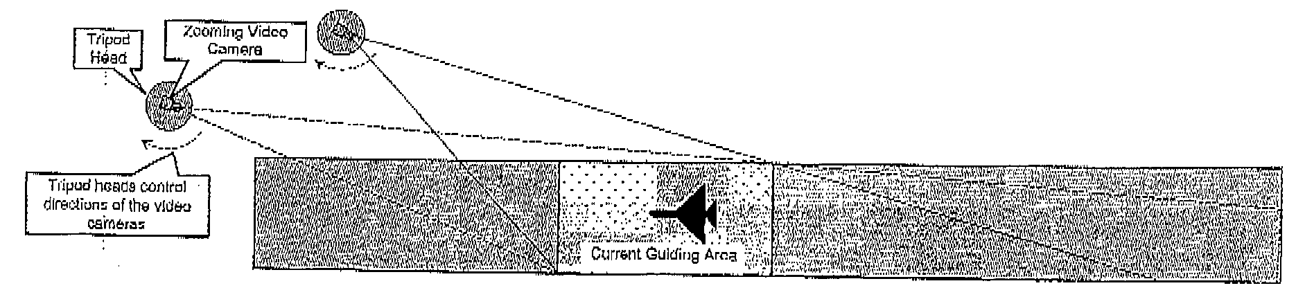
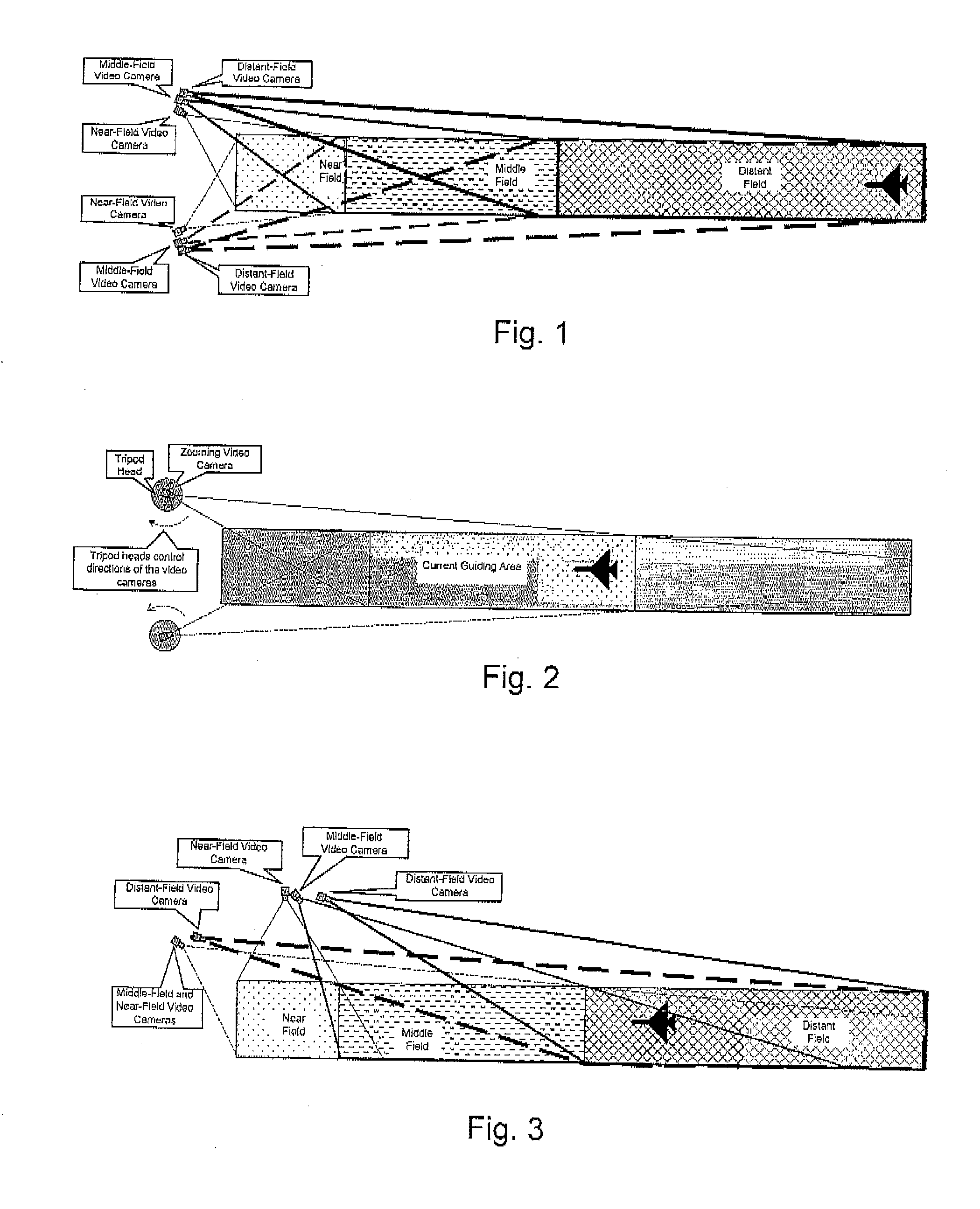
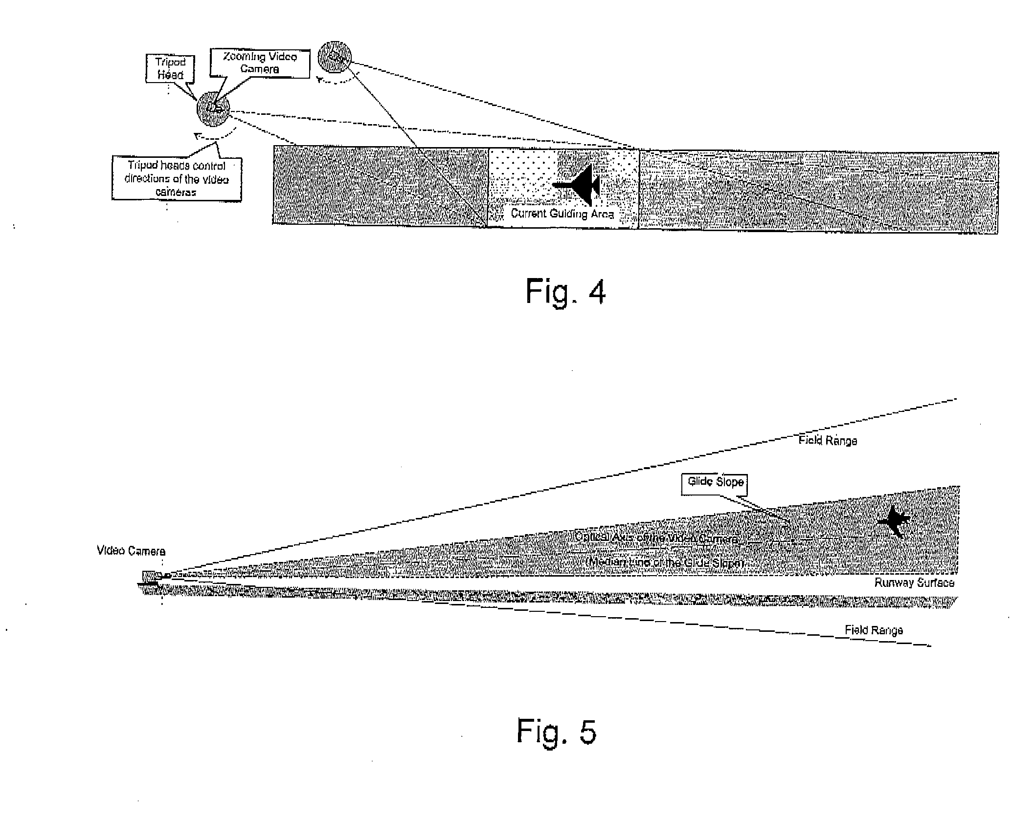
[0042](1) arranging a video camera near the landing areas of an aircraft or an unmanned aerial vechicle, the field of view of the video camera covering the flying survey area where the aircraft approaches;

[0043](2) after field installation and adjustment of the video camera is completed, calibrating video camera parameters;

[0044](3) when surveying is initiated, starting to acquire images of the survey area and detect a target in real time;

[0045](4) when the aircraft or the unmanned aerial vechicle is detected to have entered the survey area, starting to identify and extract the moving target features (such as the nose, wingtip, aircraft landing gear and landing light of the aircraft, or specially installed cooperation marks) in real time and compute a three-dimensional position, the attitude or the offset relative to the glide slope of the aircraft in real tim...


PUM


Abstract

The present invention provides a ground-based camera surveying and guiding method for aircraft landing and unmanned aerial vechicle recovery based on the camera surveying technology, which is a ground-based camera surveying and guiding system mainly including several video cameras arranged near the landing areas of an aircraft or an unmanned aerial vechicle. During the approaching process of the aircraft or the unmanned aerial vechicle, the system performs imaging of the aircraft in real time and detects movement parameters such as the track, velocity, acceleration, attitude and the offset relative to the glide slope of the aircraft or the unmanned aerial vechicle in real time by analyzing images and applying camera surveying method and technology, so as to provide guidance for aircraft landing or unmanned aerial vechicle recovery. The method is an autonomic guiding survey without interferences from others, which has high accuracy and reliability. The hardware devices are mature, simple and have low cost. The devices are moveable and versatile, and can be used in aircraft landing aid, unmanned aerial vechicle recovery and the like.

Description

CROSS-REFERENCE TO RELATED APPLICATIONS[0001]This application is a U.S. National Phase of the International Application No. PCT / CN2009 / 000327 filed on 27 Mar. 2009 designating the U.S. and published on 30 Sep. 2010 as WO 2010 / 108301.FIELD OF INVENTION[0002]The present invention relates to guiding and camera surveying techniques for aircraft landing and unmanned aerial vechicle (UAV) recovery, and the present invention further relates to providing guidance for aircraft landing and unmanned aerial vechicle recovery by surveying three-dimensional movement parameters of an aircraft or an unmanned aerial vechicle in the aircraft landing phase and during the unmanned aerial vechicle recovery in real time.DESCRIPTION OF RELATED ART[0003]Accidents take place most frequently in the aircraft landing phase and during the unmanned aerial vechicle (pilotless aircraft) recovery. Generally, a landing action is completed directly through the visual judgment result of a pilot. However, under low vis...

Claims


Application Information

Patent Timeline
Patent Type & Authority Applications(United States)
IPC IPC(8): H04N7/18
CPCG08G5/0026G01C11/00G01C21/10B64C2201/187G05D1/0676G01S5/16G08G5/025B64U70/60
Inventor YU, QIFENGLEI, ZHIHUIZHANG, XIAOHUSHANG, YANGZHANG, HENGZHOU, XIANG
Owner NAT UNIV OF DEFENSE TECH
Why Eureka
Try Eureka