Method and apparatus for providing directional navigation indication
a technology of directional navigation and indication, applied in the direction of navigation, surveying and navigation, instruments, etc., can solve the problems of limiting the current method of directional display, users using it for driving will have a hard time focusing on the information contents, and loss of actual road focus, etc., to enhance the direction navigation capabilities of said gps-enabled devi
- Summary
- Abstract
- Description
- Claims
- Application Information
AI Technical Summary
Benefits of technology
Problems solved by technology
Method used
Image
Examples
first embodiment
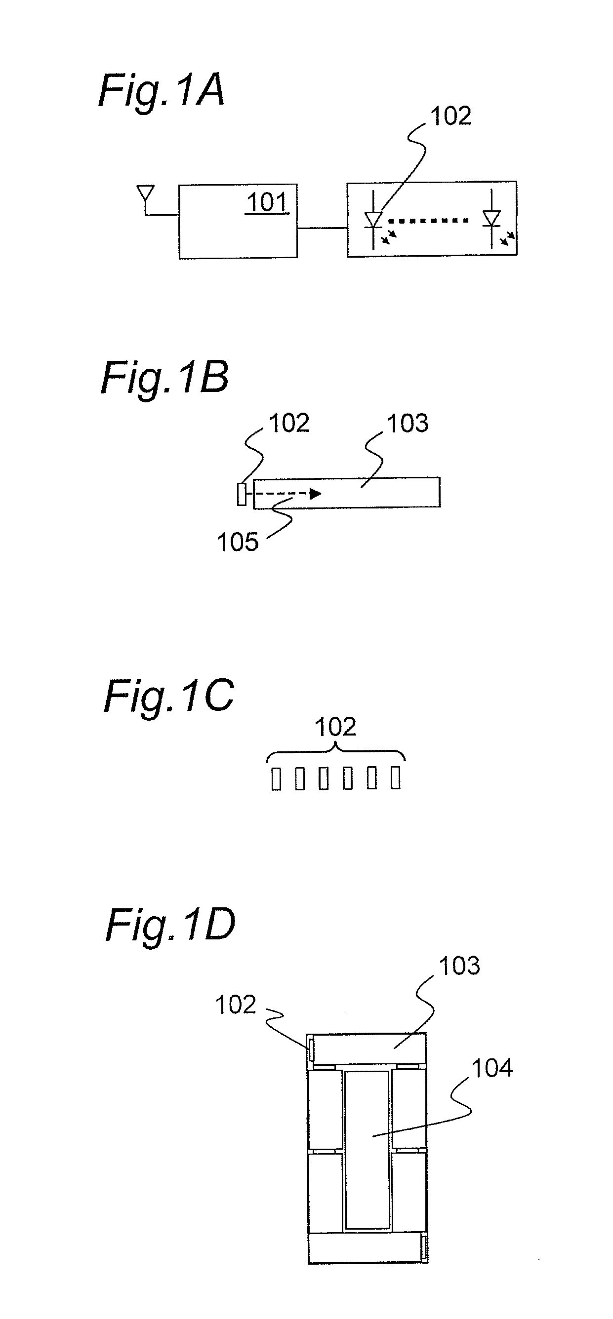
[0041]Referring to FIG. 1A, a first embodiment of a directional navigation indication apparatus on a GPS-enabled device is shown.
[0042]The directional navigation indication apparatus comprises a GPS system 101 for collecting GPS signals from a GPS signal source, such as a satellite or any GPS transmission nodes, illuminating elements 102, and light guides 103 for guiding light from the illuminating elements so as to produce a light distribution effect; and POI (point of interest) entry and verification component 104, for example a text-based entry and display screen or LCD display means.
[0043]The GPS system 101 is exemplarily represented as a GPS signal receiver and processor to output the received signal into meaningful data, where such meaningful data comprises device location and the POI (point of interest), that is, the destination of the user. The function of the antenna 100 is to capture satellite signals from the air. The GPS system converts satellite signals into actual loca...
second embodiment
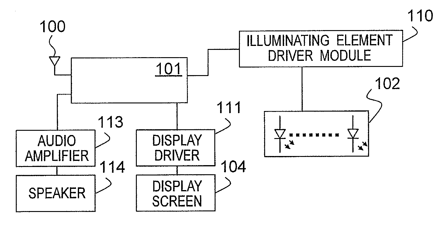
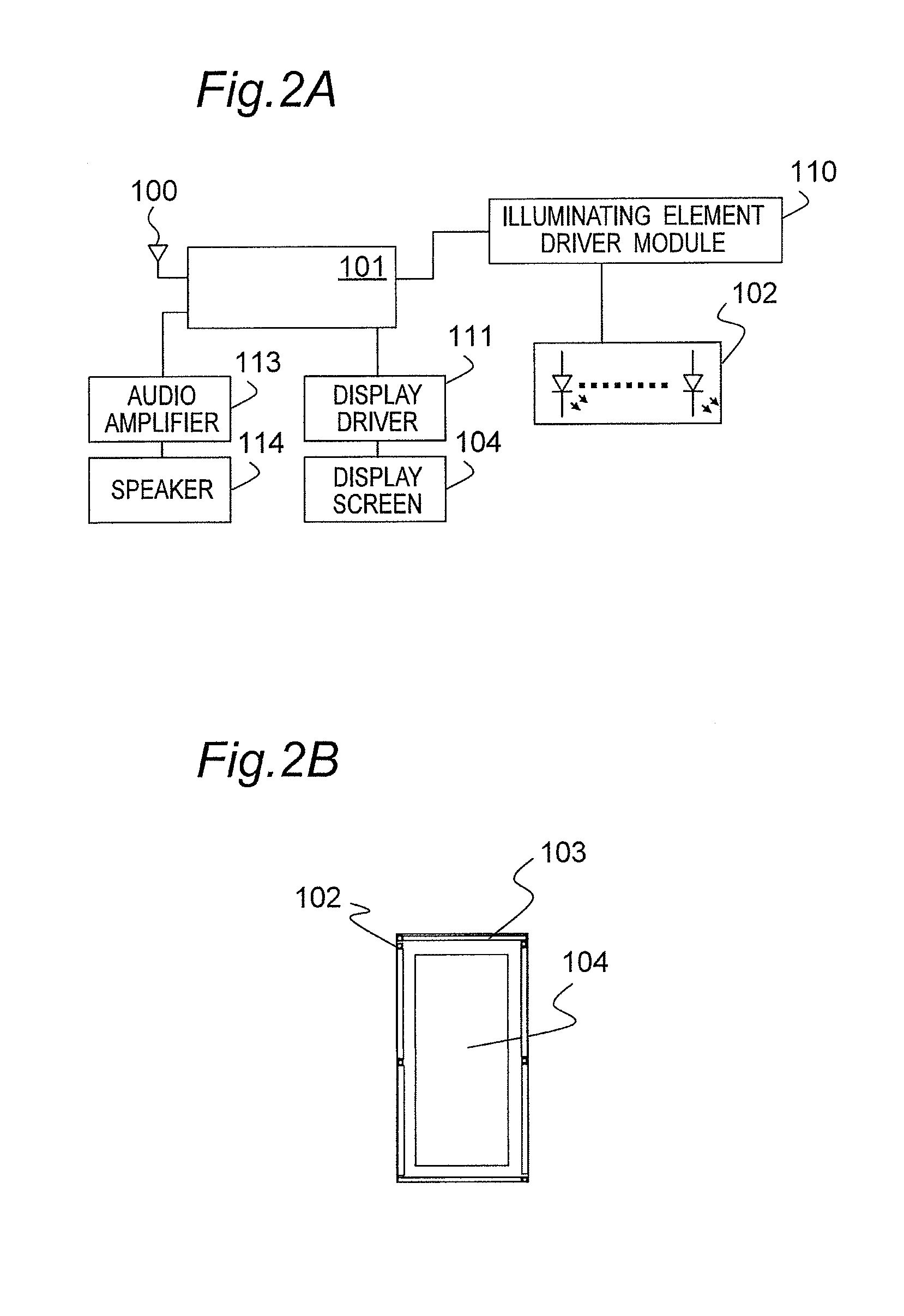
[0049]Referring to FIG. 2A, a second embodiment of the present invention is presented.
[0050]The second embodiment comprises the apparatus as described in the first embodiment, together with the addition of driver systems. The additional driver systems may exemplarily comprise at least one of or a combination of:
[0051](1) A display system, comprising of a display driver 111 and display screen 104. The display screen 104 may be exemplarily implemented using liquid crystal displays (LCDs), Organic light-emitting diodes (OLEDs) or any appropriate display types. The display system is added so as to display more roads, traffic and other information from a pre-installed map in a memory. Also, the display system may be used to exemplarily implement the POI (point of interest) entry and verification component 104;
[0052](2) An audio system, comprising of an audio amplifier 113 and a speaker 114. The audio system helps a user to navigate by providing audio direction indications;
[0053](3) A sep...
third embodiment
[0055]Referring to FIG. 3, a third embodiment of the present invention is presented. The GPS system 101 may be further comprised an RF front end 120, a GPS receiver 121 and microcontroller 122. The workings of the RF front end 120, a GPS receiver 121 and microcontroller 122 will be described as follows:
[0056]When satellite signals are captured by antenna 100, the signals go through the RF front end 120 for down conversion process. The output of the RF front end 120 is baseband IF (interface frequency). This baseband IF is then transferred into GPS receiver 121. The GPS receiver processor 121 is to detect or “lock” as many signals as possible from the output of the RF front end 120 and calculate the distance of the satellites to the earth. Once the distances of each satellite are determined, the GPS receiver 121 calculates the location on the earth through a complex algorithm. The result of the calculation is used by the microcontroller 122 to manipulate information at current locati...
PUM
 Abstract
Description
Claims
Application Information
 - R&D
- Intellectual Property
- Life Sciences
- Materials
- Tech Scout
- Unparalleled Data Quality
- Higher Quality Content
- 60% Fewer Hallucinations
Browse by: Latest US Patents, China's latest patents, Technical Efficacy Thesaurus, Application Domain, Technology Topic, Popular Technical Reports.
© 2025 PatSnap. All rights reserved.Legal|Privacy policy|Modern Slavery Act Transparency Statement|Sitemap|About US| Contact US: help@patsnap.com


