Available power estimator

a technology of available power and estimator, which is applied in the direction of instruments, machines/engines, mechanical equipment, etc., can solve the problems of not being very precise, unable to deliver all their generated power, and increasing the frequency of the electricity network, so as to improve the accuracy of any value, accurate transfer function, and accurate transfer function

Active Publication Date: 2012-03-29
SIEMENS GAMESA RENEWABLE ENERGY AS
View PDF8 Cites 37 Cited by
  • Summary
  • Abstract
  • Description
  • Claims
  • Application Information

AI Technical Summary

Benefits of technology

[0042]According to a further exemplary embodiment the calibrating of the blade pitch angle in the reference look-up table further comprises the starting of an additional calibration cycle when the turbine is derated again from a further available maximum power, so that an additional measured blade pitch angle and an additional calculated pitch angle is determined (and thus an additional pair of date). The transfer function is then additionally generated by polynomial regression (e.g. linear regression) on the basis of the differences between c) the additional measured current blade pitch angle and the additional calculated pitch angle. The more additional calibration cycle may be provided, the more accurate the transfer function will be.
[0043]In particular, a self learning algorithm for independently improving the transfer function may be achieved. Every time when the wind turbine runs with the achievable maximum power and is derated to a limited power again, a new additional calibration cycle may be started as described above. At the end of such an additional calibration cycle a further additional measured current blade pitch angle and a further additional calculated pitch angle (an additional pair of data) is determined with which the transfer function is then additionally generated by polynomial regression on the basis of the differences (offset) between the further additional measured current blade pitch angle and the further additional calculated pitch angle

Problems solved by technology

This is based on the fact that the wind turbines, which are connected to the electricity network, cannot deliver all their generated power to the electricity network.
Therefore, a power imbalance, wherein the produced power is larger than the used power, may result in

Method used


Image

  • Available power estimator
  • Available power estimator
  • Available power estimator

Examples


Embodiment Construction

[0062]The illustrations in the drawings are schematic. It is noted that in different figures similar or identical elements are provided with the same reference signs.

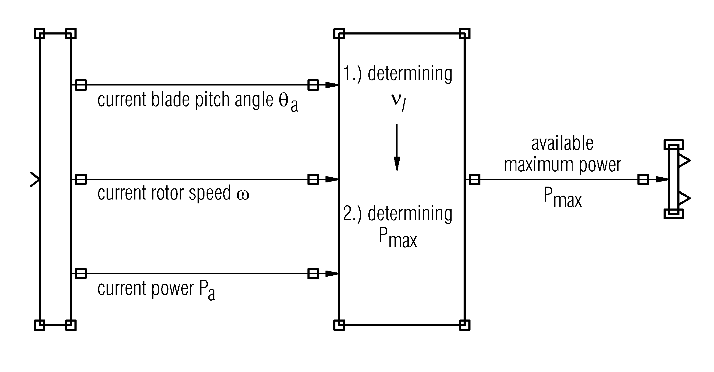
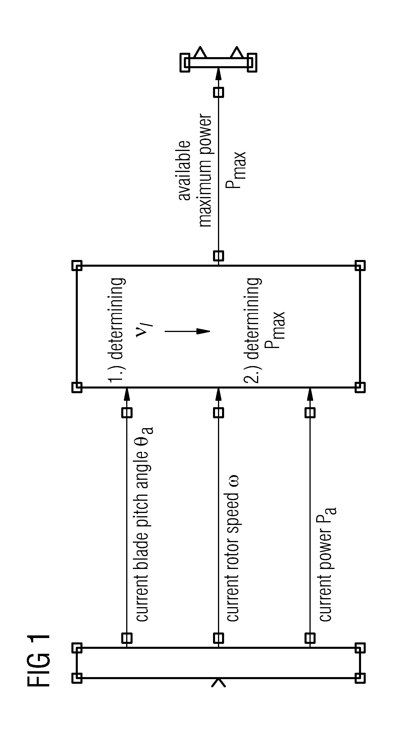
[0063]FIG. 1 shows an exemplary embodiment of the method of determining an estimated wind speed νe of a wind driving a wind turbine 900 (see FIG. 9). The method comprising measuring a current power Pa being generated by the wind turbine 900, measuring a current rotor speed ωa of a rotor 903 (see FIG. 9) of the wind turbine 900 and measuring a current blade pitch angle θa of a rotor blade 901 (see FIG. 9) of the rotor 903. Based on the current power Pa, the current rotor speed ωa and the current blade pitch angle ea, the estimated wind speed νe may be determined.

[0064]As can be taken from FIG. 1, the determining of the estimated wind speed νe under step 1 may lead to a determination of the maximum available power Pmax under step 2, even when the wind turbine 900 is down-regulated, i.e. when the wind turbine 900 produces ...


PUM


Abstract

A method of determining an estimated wind speed of a wind driving a wind turbine includes measuring a current power generated by the wind turbine, measuring a current rotor speed of a rotor of the wind turbine, and measuring a current blade pitch angle of a rotor blade of the rotor. Moreover, the method includes determining the estimated wind speed based on the current power, the current rotor speed and the current blade pitch angle.

Description

FIELD OF INVENTION[0001]The present invention relates to a method of determining an estimated wind speed of a wind driving a wind turbine and an estimating device for determining an estimated wind speed of a wind driving a wind turbine. Further, the present invention relates to a wind turbine and a wind farm arrangement. Moreover, the present invention relates to a computer program for processing an estimating device of a wind turbine.ART BACKGROUND[0002]Wind energy is increasingly recognized as a viable option for complementing and even replacing other types of energy sources such as for instance fossil fuels. In the early development of wind energy, the majority of wind turbines were constructed for operation at a constant speed. However, recently the trend is toward using variable-speed wind turbines to better capture available wind power. In most cases, wind turbine blade pitch angles can be adjusted to control the operation of the variable speed wind turbine.[0003]When the elec...

Claims


Application Information

Patent Timeline
IPC IPC(8): G01W1/00G06F19/00G06Q10/00G06Q50/00
CPCG06Q50/06G06Q10/04F05B2260/821F05B2270/32F05B2270/327F05B2270/328F05B2270/335F03D17/00Y02E10/72Y02E10/70
Inventor KRISHNA, RAMAKRISHNAN
Owner SIEMENS GAMESA RENEWABLE ENERGY AS
Why Eureka
Try Eureka