Battery module mounting structure for motor-driven two-wheeled vehicle

a two-wheeled vehicle and battery module technology, which is applied in the direction of vehicle sub-unit features, cycle equipment, optical signals, etc., can solve the problems of increasing the number of dedicated mounting parts, complicated assembly work, and not allowing for the increase of assembly work efficiency, so as to achieve the effect of easy mounting and dismounting

Inactive Publication Date: 2012-04-05
HONDA MOTOR CO LTD
View PDF20 Cites 23 Cited by
  • Summary
  • Abstract
  • Description
  • Claims
  • Application Information

AI Technical Summary

Benefits of technology

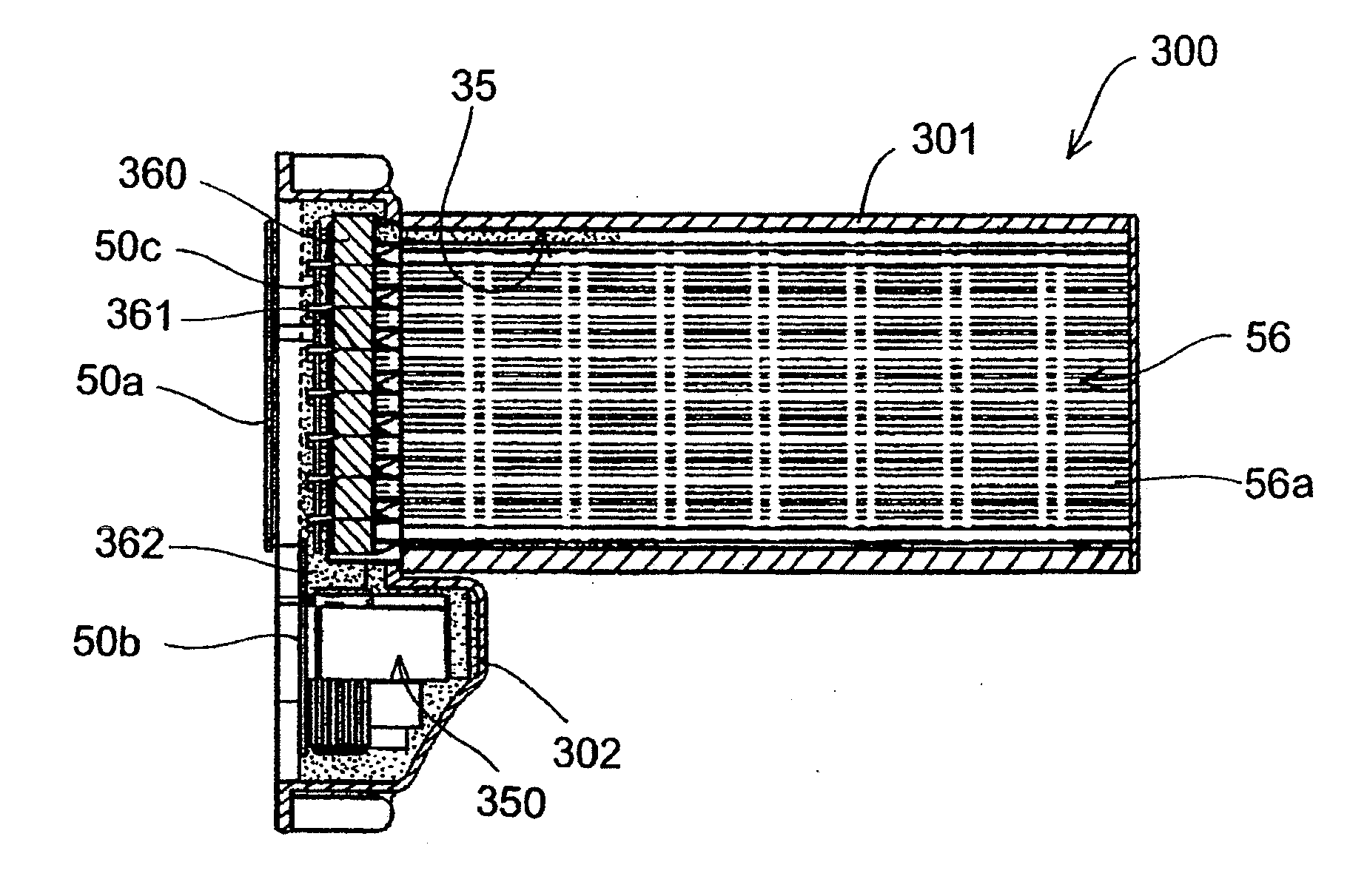
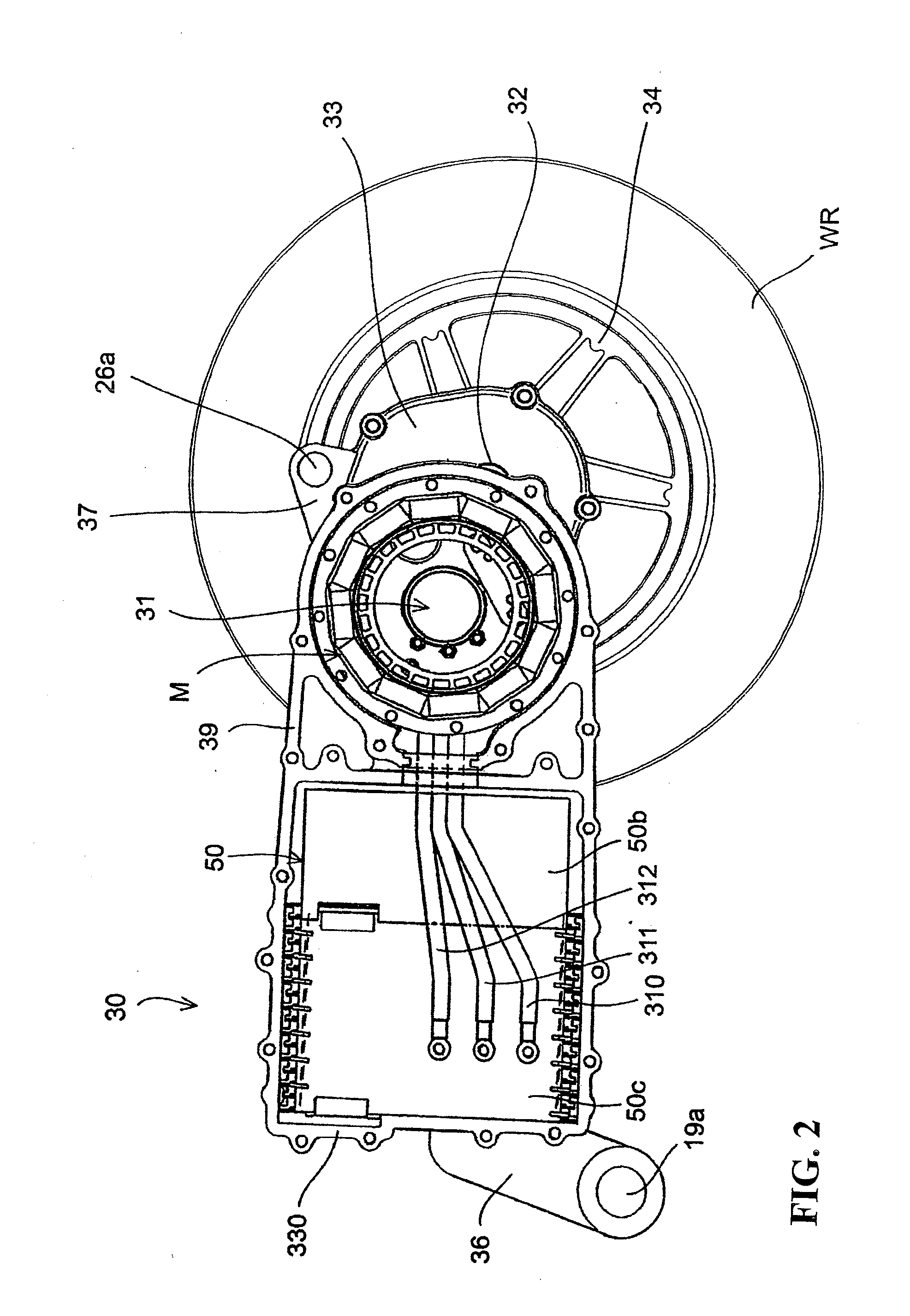
[0019]According to an embodiment of the present invention, the battery module mounting structure includes the housing structure housing the battery supplying electric power to the electric motor and the PDU controlling the electric motor. In addition, the housing case is configured to be mountable to and dismountable from the swing arm with the battery and the PDU housed in the housing case. Therefore, the battery and the substrates can be handled as a module mountable to and dismountable from the swing arm. This makes it possible to previously perform the temporary assembling work for securing the battery and the like to the housing case. Thus, the swing arm assembly efficiency can be improved. In addition, the work for replacing the battery after the completion of the vehicle can be facilitated and the general versatility in which a communalized housing case is applied to a variety of swing arms can be enhanced. Since the housing case and the housed parts can collectively be designed, they can easily be designed while optimizing the balance of the center of gravity of the entire module.
[0028]According to an embodiment of the present invention, the housing case is composed of the battery housing portion housing the battery and the heater element housing portion housing the heater element. Therefore, the battery and the heater element substrate can be divided and be housed so that they can more effectively avoid the mutual thermal influence therebetween.

Problems solved by technology

Therefore, the number of dedicated mounting parts is increased and the assembly work is complicated.
In addition, the technology described in Japanese Patent Laid-Open No. 2008-221976 does not allow for the increased efficiency of assembling work and enhanced maintenance performance by making is possible to mount and dismount these power system parts to and from the vehicle body.

Method used


Image

  • Battery module mounting structure for motor-driven two-wheeled vehicle
  • Battery module mounting structure for motor-driven two-wheeled vehicle
  • Battery module mounting structure for motor-driven two-wheeled vehicle

Examples


Embodiment Construction

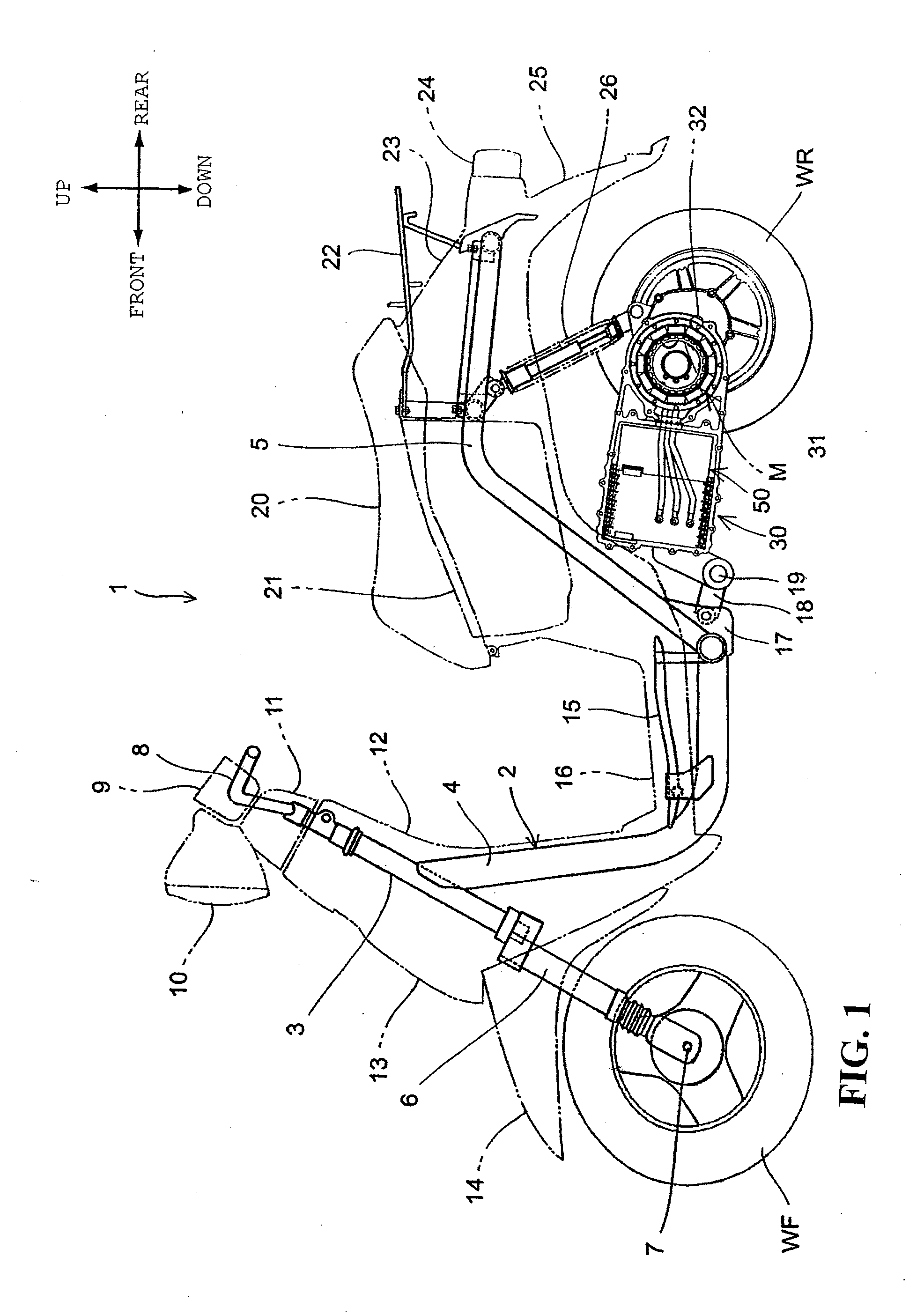
[0042]Preferred embodiments of the present invention will hereinafter be described in detail with reference to the drawings. FIG. 1 is a lateral view of a motor-driven two-wheeled vehicle 1 according to an embodiment of the present invention. The motor-driven two-wheeled vehicle 1 is a scooter-type, straddle-ride type vehicle having a low-floor 16. A rear wheel WR is driven by an electric motor M housed in a swing arm unit 30. A head pipe 3 turnably supporting a stem shaft (not shown) is joined to a front portion of a body frame 2. A steering handlebar 8 covered by a handlebar cover 11 is joined to an upper portion of the stem shaft. A pair of left and right front forks 6 is joined to a lower portion of the stem shaft. The front forks 6 rotatably support a front wheel WF via an axle 7.

[0043]The body frame 2 includes a main pipe 4 extending downward from a rear portion of the head pipe 3 and a rear frame 5 connected to a rear end portion of the main pipe 4 and extending upward and to...


PUM


Abstract

A battery module mounting structure includes a housing structure housing a battery supplying electric power to the electric motor of a motor-driven two-wheeled vehicle and a PDU controlling the electric motor. The housing case is configured to be mountable to and dismountable from the swing arm with the electric motor and a control substrate housed in the housing case. The swing arm is formed as a cantilever type in which an arm portion disposed on the vehicle-widthwise right or left of a rear wheel supports the rear wheel. The battery shaped in a rectangular parallelepiped is housed in the housing case with a longitudinal direction thereof facing in a vehicle-width direction. The housing case is mounted from a vehicle-widthwise inside on a lateral surface of a swing arm housing at a position vehicle-body-forward of the rear wheel and vehicle-body-rearward of a through-hole, the swing arm housing supporting the arm portion.

Description

CROSS-REFERENCE TO RELATED APPLICATIONS[0001]The present application claims priority under 35 USC 119 to Japanese Patent Application No. 2010-222877 filed on Sep. 30, 2010 the entire contents of which are hereby incorporated by reference.BACKGROUND OF THE INVENTION[0002]1. Field of the Invention[0003]The present invention relates generally to a battery module mounting structure for a motor-driven two-wheeled vehicle. More particularly, to a battery module mounting structure for a motor-driven two-wheeled vehicle in which a motor as a power source is driven by electric power supplied from an in-vehicle battery.[0004]2. Description of Background Art[0005]It has been considered in motor-driven two-wheeled vehicles traveling by use of a motor as a power source, to optimize the arrangement and structure of a high-voltage battery supplying electric power to a motor and of a motor control unit.[0006]Japanese Patent Laid-Open No. 2008-221976 discloses a motor-driven two-wheeled vehicle with...

Claims


Application Information

Patent Timeline
Patent Type & Authority Applications(United States)
IPC IPC(8): B60K1/04
CPCB60G2206/0114B62K2208/00B60K7/0007B60K17/043B60K2001/0416B60K2007/0038B60K2007/0061B60L11/1822B60Y2200/126B62M7/12B60Y2400/61B62J6/001Y02T10/7005Y02T10/7072Y02T90/124Y02T90/14B60L11/1877Y02T10/705B62K2202/00B62K11/10B60K2001/008B60K1/04B60L53/80B60L50/66B62J6/01Y02T10/70B62J43/16B62J43/20Y02T90/12
Inventor TSUKAMOTO, TOMOHIROSHIBATA, KAZUMITOMINAGA, TAKASHIAKUTSU, SUSUMU
Owner HONDA MOTOR CO LTD
Why Eureka
Try Eureka