
Aircraft engine attachment pylon comprising two front wing system attachments with orthogonal shearing pins

a technology of attachment pylon and engine, which is applied in the direction of aircraft power plants, power plant construction, power plant types, etc., can solve the problems of increasing the diameter of the fan case, and increasing the size of the engine, so as to achieve the effect of reducing the overall mass and bulk, non-negligently reducing the cost of the attachment pylon and the overall mass

Inactive Publication Date: 2012-04-05
AIRBUS OPERATIONS INC AS A
View PDF12 Cites 27 Cited by
  • Summary
  • Abstract
  • Description
  • Claims
  • Application Information

AI Technical Summary

Benefits of technology

[0030]Thus, eliminating this intermediate cleat advantageously creates a decrease in the mass and bulk relative to the attachment means, and consequently a non-negligible decrease in the overall mass and the cost of the attachment pylon.
[0031]Moreover, the decreased bulk makes it possible to come closer to the rigid structure of the attachment pylon of the lower part of the wing.
[0033]The assembly according to the invention consequently allows an increase in the dimensions of the rigid structure of the attachment pylons, thereby making it possible to make them better adapted to the significant forces they must take up.

Problems solved by technology

In fact, on the turboshaft engines of recent aircrafts, the high dilution level sought leads to obtaining an extremely high bulk, since increasing the dilution level inevitably leads to an increase in the diameter of the engine, and more particularly an increase in the diameter of its fan case.
Thus, with a ground clearance that is naturally set so as to remain acceptable from a safety perspective, the space remaining between the wing and the turboshaft engine serving to house the rigid structure of the attachment pylon as well as its different attachments is more and more limited, while paradoxically, the forces to be taken up are of course increasingly high.
This evolution of turboshaft engines has had the harmful consequence of imposing a reduction of the vertical dimensions of the rigid structure of the attachment pylon, in particular so as to be able to keep sufficient space to place the component elements of the intermediate attachment, the large dimensions of which are imposed by the need to take up thrust forces from the turboshaft engine, i.e. those oriented in the longitudinal direction of said turboshaft engine.
Furthermore, providing four distinct wing system attachments inevitably leads to a high overall mass for the attachment pylon.

Method used


Image

  • Aircraft engine attachment pylon comprising two front wing system attachments with orthogonal shearing pins
  • Aircraft engine attachment pylon comprising two front wing system attachments with orthogonal shearing pins
  • Aircraft engine attachment pylon comprising two front wing system attachments with orthogonal shearing pins

Examples


Embodiment Construction

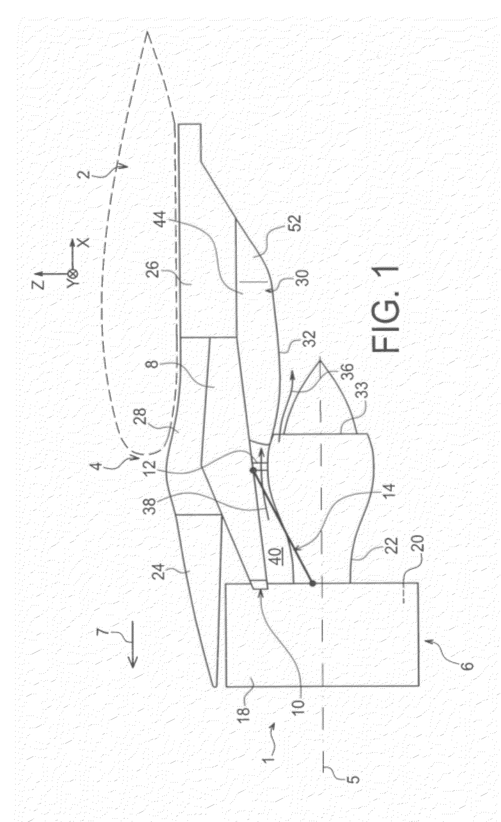
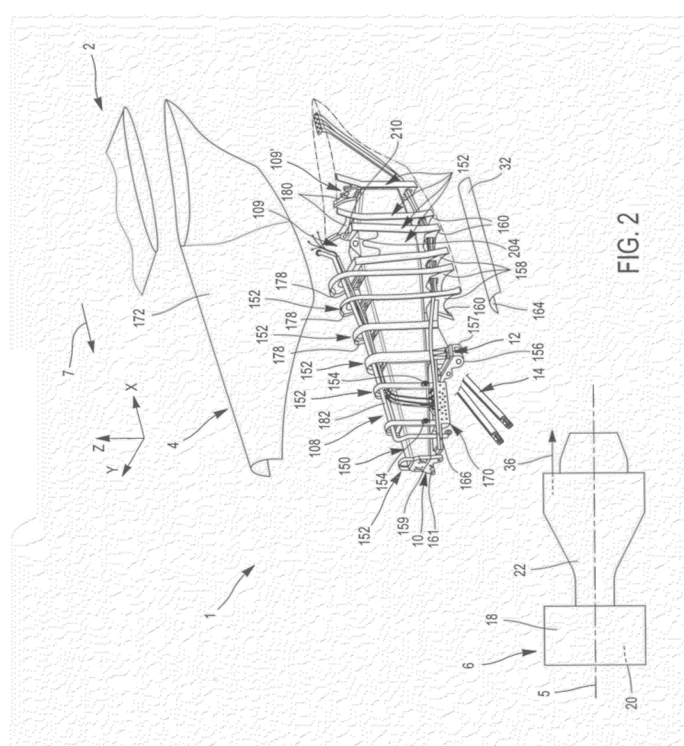
[0054]FIG. 2 shows an exploded view of an aircraft engine assembly intended to be fastened under a wing 2 of said aircraft, this assembly 1 including an attachment device 4 intended to be an integral part of an aircraft assembly according to one preferred embodiment of the present invention.

[0055]In this assembly 1, which also includes an engine 6 such as a turbojet engine attached under the device 4, certain elements are identical or similar to those of the prior art assembly shown in FIG. 1. In this respect, in the figures, elements bearing the same numbers correspond to identical or similar elements.

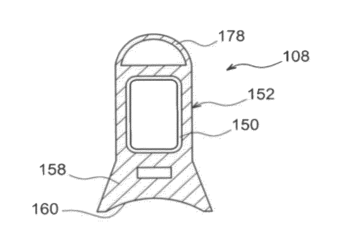
[0056]The attachment pylon 4 includes a rigid structure 108, also called primary structure, bearing attachment means for the engine 6, these attachment means having a plurality of engine attachments 10, 12 (each shown in part only in FIG. 2), as well as a take-up device for thrust forces 14 generated by the engine 6.

[0057]For information, it should be noted that the assembly 1 is inte...


PUM


Abstract

The present invention relates to an aircraft assembly (200) comprising a wing (2) and an engine attachment pylon (4) fixed to the wing by means of attachment means comprising a first and a second front wing system cleat (109, 109) connecting a rigid structure (108) of the attachment pylon and a front longeron (201) of the wing. The first front wing system cleat (109) comprises a first shearing pin (202) oriented in the transversal direction (Y) to ensure take-up of forces exerted in the longitudinal (X) and vertical (Z) directions of the pylon, and the second front wing system cleat (109) comprises a second shearing pin (208) oriented in the longitudinal direction (X) to ensure take-up of forces exerted in the transversal (Y) and vertical (Z) directions of the pylon.

Description

TECHNICAL FIELD[0001]The present invention relates to an aircraft engine attachment pylon intended to be inserted between an aircraft wing system and the concerned engine, and more particularly an assembly comprising this same pylon mounted on a wing of the aircraft.[0002]This type of attachment pylon, or EMS (Engine Mounting Structure), makes it possible to suspend an engine below the wing system of the aircraft, or to mount said turboshaft engine above that same wing system.[0003]The invention can be used on any type of aircraft preferably equipped with turbojet engines or turboprops.BACKGROUND OF THE INVENTION[0004]Such an attachment pylon is in fact provided to form the connecting interface between an engine and a wing of the aircraft. It makes it possible to transmit, to the structure of said aircraft, the forces generated by its associated engine, and also allows the conveyance of the fuel, the electrical, hydraulic and air systems between the engine and the aircraft.[0005]FIG...

Claims


Application Information

Patent Timeline
Patent Type & Authority Applications(United States)
IPC IPC(8): B64D27/26B64D27/02
CPCB64D27/18B64D27/40
Inventor LAFONT, LAURENTJOURNADE, FRÉDÉRICRENAUD, ERIC
Owner AIRBUS OPERATIONS INC AS A
Features
  • Generate Ideas
  • Intellectual Property
  • Life Sciences
  • Materials
  • Tech Scout
  • Unparalleled Data Quality
  • Higher Quality Content
  • 60% Fewer Hallucinations
Learn More