Wind power converting apparatus

a technology of wind power conversion and rotary blades, which is applied in the direction of electric generator control, renewable energy generation, greenhouse gas reduction, etc., can solve the problems of limited wind power conversion apparatuses of the related art, and achieve the effect of increasing the rotational force of the rotary blade assembly and increasing the operating efficiency of the wind power conversion apparatus

Inactive Publication Date: 2012-04-05
JU YOUNG DAE
View PDF6 Cites 7 Cited by
  • Summary
  • Abstract
  • Description
  • Claims
  • Application Information

AI Technical Summary

Benefits of technology

[0025]According to an aspect of the present invention, the wind power converting apparatus is provided with the cover, which prevents a headwind, which blows opposite to the direction in which the rotary blade assembly rotates, from being introduced to the rotary blade assembly, or with the auxiliary blades, which protrude from the surface of the rotary blade assembly in order to increase the rotational force of the rotary blade assembly using the wind that is introduced from the outside. This configuration provides effects such that the operating efficiency of the wind power converting apparatus is increased, power generation is possible even in light wind, and a plurality of generators can be connected together.

Problems solved by technology

However, wind power converting apparatuses of the related art are limited in the extent to which the generation efficiency thereof can be improved, in consideration of their structures.

Method used


Image

  • Wind power converting apparatus
  • Wind power converting apparatus
  • Wind power converting apparatus

Examples


first embodiment

[0096]Descriptions will be given below of the other embodiments of the present invention with reference to the accompanying drawings. In the following, descriptions of some features will be omitted, since they are identical to those of the above-described first embodiment of the present invention.

[0097]FIG. 5 is a perspective view showing a wind power converting apparatus according to a second embodiment of the present invention, from which a rotor unit is disassembled, and FIG. 6 is a perspective view showing the wind power converting apparatus according to the second embodiment of the present invention, to which the rotor unit is assembled.

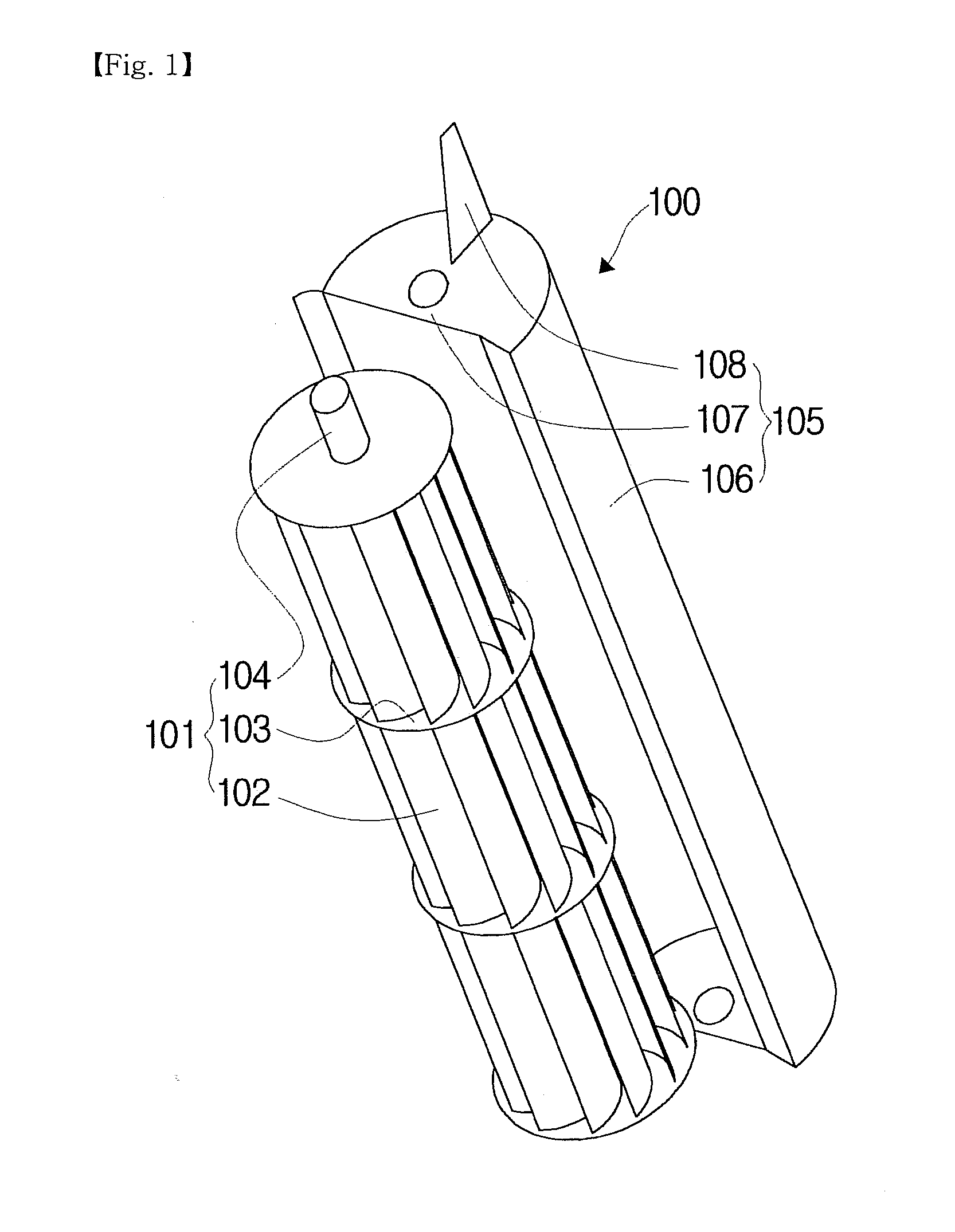
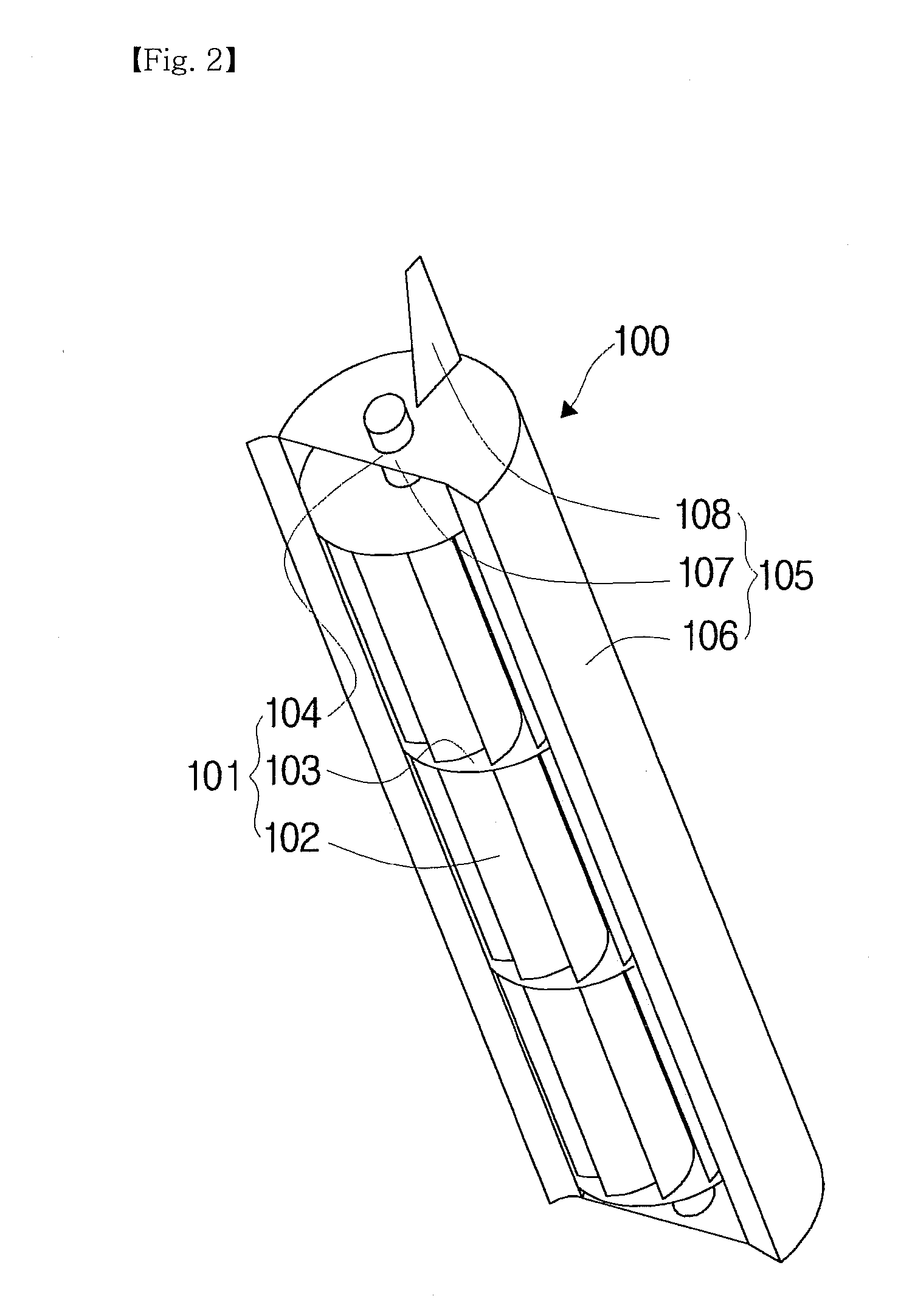
[0098]Referring to FIG. 5 and FIG. 6 together, in this embodiment, a rotary shaft 124 of a rotary blade assembly 121 of a rotor unit 120 is oriented horizontally with respect to the ground on which it is disposed, and a cover 125, which surrounds part of the rotary blade assembly 121, is also oriented horizontally.

[0099]In this embodiment, wind ...

fourth embodiment

[0102]FIG. 9 is a perspective view showing part of a rotor unit of a wind power converting apparatus according to the present invention.

[0103]Referring to FIG. 9, in this embodiment, a wind guide 148 is configured such that its length is variable with respect to the body 146 of a cover 145. The length of the wind guide 148 can be manually changed by an operator, or can be automatically changed by a controller (not shown), a drive motor and the like, by sensing the intensity of the wind.

[0104]When the length of the wind guide 148 is variable as described above, the length of the wind guide 148 can be changed depending on the intensity of the wind, such that the rotation of the rotary blade assembly 141 can be adjusted, so that the rotary blade assembly 141 becomes suitable for power generation so as to be exposed to more wind, thereby increasing the operating efficiency.

fifth embodiment

[0105]FIG. 10 is a perspective view showing a rotary blade, which is applied to a rotor unit of a wind power converting apparatus according to the present invention.

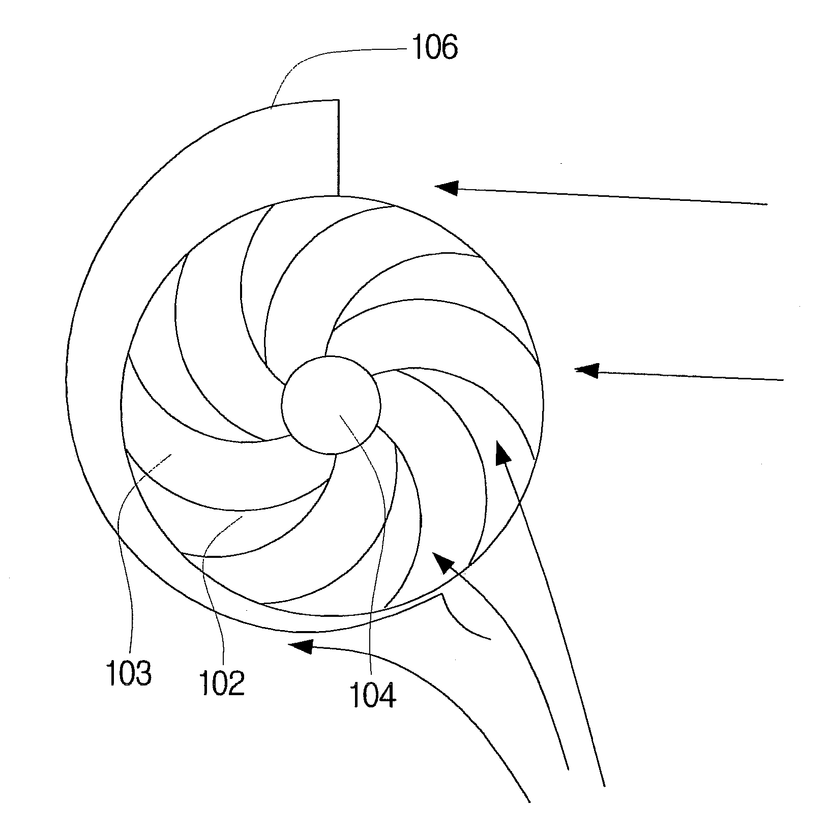
[0106]Referring to FIG. 10, in this embodiment, a rotor unit 150 includes a rotary shaft 154, rotary blades 152 and auxiliary blades 155, and is intended to rotate while the wind is introduced from the outside in the direction perpendicular to the rotary shaft 154.

[0107]Each rotary blade 152 extends in a curve from the rotary shaft 154.

[0108]The auxiliary blades 155 protrude from the surface of the rotary blade 152 in order to increase the rotational force of the rotary blade 152 using the wind that is introduced thereto from the outside. The direction in which the auxiliary blades 155 protrude may be set at an acute angle with respect to the surface of the rotary blade 152. The auxiliary blades 155 may have a width that is the same as that of the rotary blade 152, or may be formed in a structure in which they are divide...


PUM


Abstract

A wind power converting apparatus that includes a rotor unit. The rotor unit includes a rotary blade assembly and a cover. The rotary blade assembly has a rotary blade disposed in the longitudinal direction of the rotary shaft, and is rotated by the wind from the outside. The cover blocks a headwind, which blows opposite to the direction in which the rotary blade assembly is rotated, from being introduced to the rotary blade assembly. According to the wind power converting apparatus, the operating efficiency of the wind power converting apparatus is increased, power generation is possible even in light wind, and a plurality of generators can be connected together.

Description

TECHNICAL FIELD[0001]The present invention relates to a wind power converting apparatus.BACKGROUND ART[0002]Wind power converting apparatuses are apparatuses that generate electricity from wind power, or use wind power as a kinetic force, or the like.[0003]Such a wind power converting apparatus generates electricity using the wind that blows from the outside, and includes a rotor unit, which has rotary blades, and a generator unit, which rotates together with the rotation of the rotary blades, to thus generate electricity.[0004]However, wind power converting apparatuses of the related art are limited in the extent to which the generation efficiency thereof can be improved, in consideration of their structures. Therefore, it is demanded that the structure of wind power converting apparatuses be improved in order to increase the generation efficiency thereof.DISCLOSURETechnical Problem[0005]An object of the present invention is to provide a wind power converting apparatus, which is co...

Claims


Application Information

Patent Timeline
Patent Type & Authority Applications(United States)
IPC IPC(8): F03D9/00F03D5/00
CPCF03D3/00F03D3/002F03D3/0436F05B2240/302Y02E10/74F03D3/0481F03D3/065F03D3/0454F03D15/10F03D9/25F03D9/32F03D3/062
Inventor JU, YOUNG-DAE
Owner JU YOUNG DAE
Why Eureka
Try Eureka