Control device

a control device and control device technology, applied in the direction of vehicle position/course/altitude control, process and machine control, instruments, etc., can solve the problems of poor robustness of vibration suppression control, frequency of power transmission system, and inability to appropriately suppress torsional, so as to reduce the output torque of rotating electrical machines and avoid unnecessary execution of damping control. , the effect of enhancing energy efficiency

Inactive Publication Date: 2012-04-05
AISIN AW CO LTD
View PDF2 Cites 29 Cited by
  • Summary
  • Abstract
  • Description
  • Claims
  • Application Information

AI Technical Summary

Benefits of technology

[0017]According to this fifth aspect, unnecessary execution of the damping control is prohibited, whe...

Problems solved by technology

Thus, the inventor has found that the configuration that continuously changes a command value of damping torque that is output from the rotating electrical machine as in the above vibration suppression control device cannot appropriately suppress the torsional vibration of the power...

Method used


Image

  • Control device
  • Control device
  • Control device

Examples


Embodiment Construction

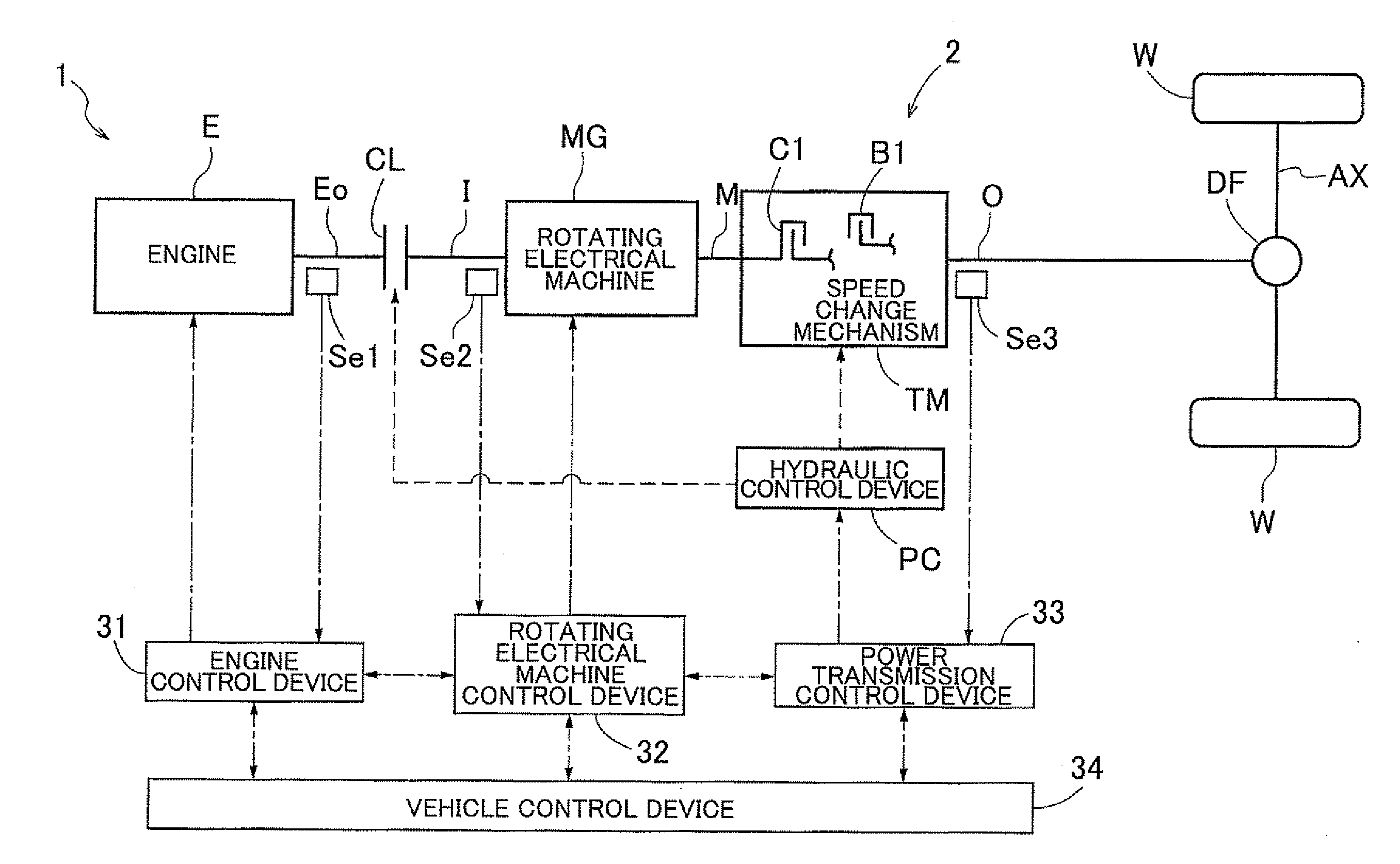
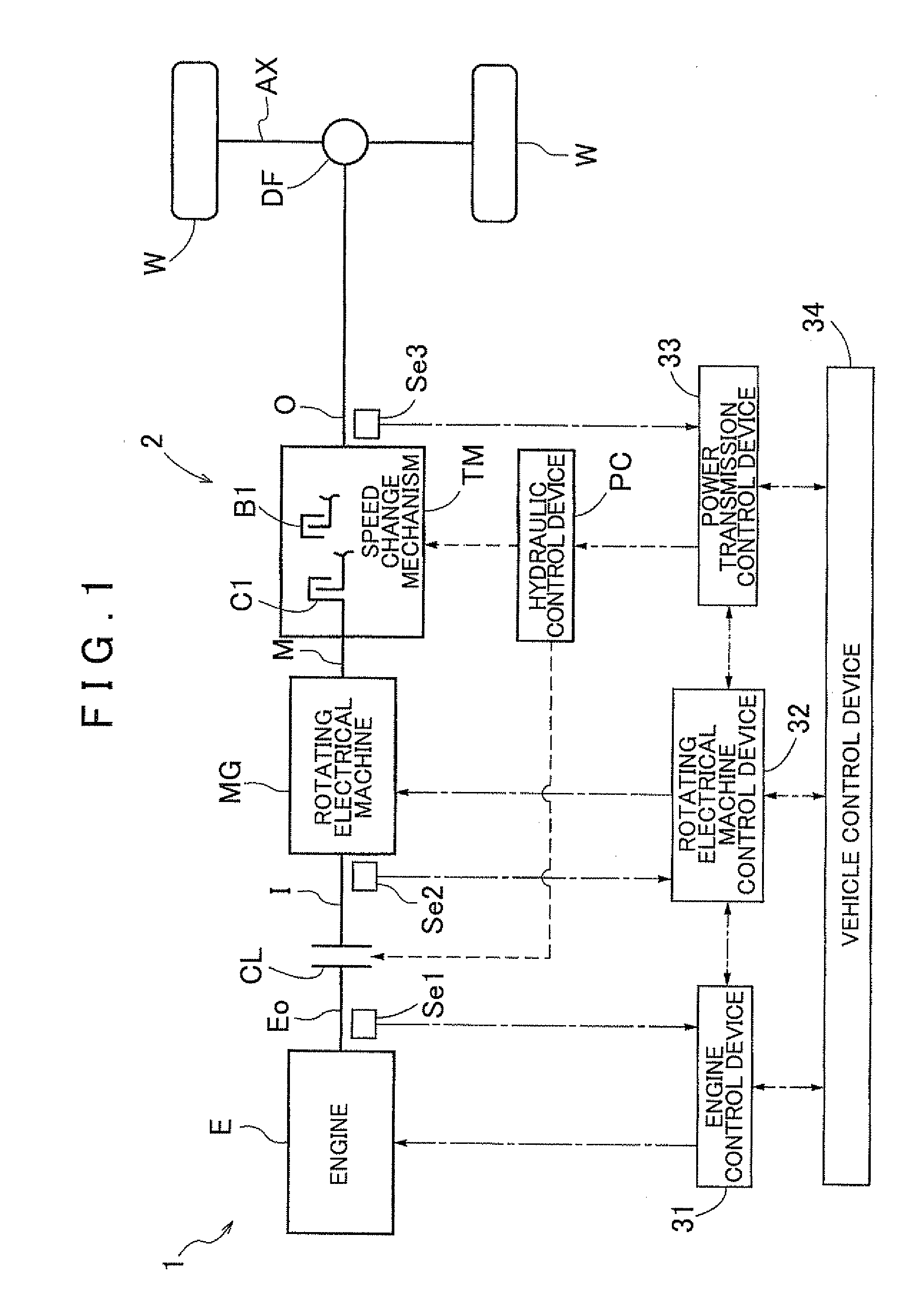
[0028]An embodiment of a rotating electrical machine control device 32 according to the present invention will be described below with reference to the accompanying drawings. FIG. 1 is a schematic diagram showing a general configuration of a vehicle drive device 1 according to the present embodiment. As shown in the drawing, a vehicle having the vehicle drive device 1 mounted thereon is a hybrid vehicle including as driving force sources an engine E as an internal combustion engine and a rotating electrical machine MG. In this drawing, solid lines represent a transmission path of a driving force, broken lines represent a supply path of hydraulic oil, and chain lines represent a transmission path of a signal. As shown in the drawing, the rotating electrical machine MG of the present embodiment is selectively drivingly coupled to the engine E according to an engagement state of an engine disconnect clutch CL, and is drivingly coupled to wheels W via a power transmission mechanism 2. T...


PUM


Abstract

A control device capable of executing damping control of outputting a damping torque command that suppresses vibration of a rotational speed of a rotating electrical machine caused at least by elastic vibration of a power transmission mechanism. This is accomplished by using feedback control based on the rotational speed of the rotating electrical machine. The control device executes the damping control by a direct-coupling damping controller when the engagement state of the engagement device is a direct-coupling engagement state in which there is no rotational speed difference between engagement members, and executes the damping control by a non-direct-coupling damping controller different from the direct-coupling damping controller in a case where the engagement state of the engagement device is a non-direct-coupling engagement state other than the direct-coupling engagement state.

Description

INCORPORATION BY REFERENCE[0001]The disclosure of Japanese Patent Application No. 2010-221883 filed on Sep. 30, 2010 including the specification, drawings and abstract is incorporated herein by reference in its entirety.BACKGROUND OF THE INVENTION[0002]The present invention relates to control devices for controlling a rotating electrical machine that is selectively drivingly coupled to an internal combustion engine in accordance with an engagement state of an engagement device, and that is drivingly coupled to a wheel via a power transmission mechanism.DESCRIPTION OF THE RELATED ART [0003]Regarding such a control device, a technique of a vibration suppression control device as shown below is disclosed in, e.g., Japanese Patent Application Publication No. JP-A-2004-322947 below. This vibration suppression control device is applied to a drive system as in, e.g., a series / parallel type hybrid vehicle, in which a natural frequency and an attenuation factor of a power transmission system...

Claims


Application Information

Patent Timeline
IPC IPC(8): B60W10/08B60W20/00B60W10/11B60L50/16
CPCB60K2006/4825Y02T10/70B60W10/02B60W10/08B60W10/115B60W20/00B60W30/19B60W30/20B60W50/0098B60W2050/0009B60W2050/0056B60W2510/0208B60W2510/081B60W2510/1005B60W2710/081Y02T10/6252Y02T10/7258Y02T10/7077B60L11/14B60L50/16Y02T10/62Y02T10/7072Y02T10/72B60W2510/102B60W20/40
Inventor IZAWA, JINKOBAYASHI, YASUHIKO
Owner AISIN AW CO LTD
Why Eureka
Try Eureka