
Hydraulic Brake Master Cylinder with Back-up Ring

a hydraulic brake and master cylinder technology, applied in the direction of cycle brakes, fluid couplings, cycle equipments, etc., can solve the problems of premature wear, catastrophic failure, and rapid backward oscillation of the piston bor

Active Publication Date: 2012-04-12
PERFORMANCE SYST
View PDF4 Cites 13 Cited by
  • Summary
  • Abstract
  • Description
  • Claims
  • Application Information

AI Technical Summary

Benefits of technology

[0007]In another embodiment, the hydraulic master cylinder with back-up ring relates to a method of operating a brake master cylinder that includes actuating a piston assembly having a piston and a cup seal, wherein the cup seal is in contact with a bore wall of the master cylinder, supporting at least a portion of the cup seal situated adjacent to the bore wall, passing the cup seal over a port timing hole opening in the bore wall during actuation of the piston; and preventing the at least a portion of the cup seal from extruding into the port timing hole opening during actuation of the piston.

Problems solved by technology

In addition, when ABS is activated, the piston in the piston bore oscillates rapidly back and forth exerting substantial stress on the cup seals.
The higher pressure, along with the violent reciprocation of the piston during ABS activation, can result in premature wear as well as damage to the cup seals, which can result in a catastrophic failure.
Although the central valve can reduce the wear and damage of a cup seal by allowing bore cavity pressure to vent through the piston, numerous drawbacks exist with a central valve system.
More particularly, a master cylinder assembly that utilizes a central valve contains several additional parts, which increase cost of manufacturing.
In addition, the required valve actuation of the central valve can decrease the reliability of a master cylinder assembly, as additional moving parts are required to operate.
Further, the use of a central valve can increase lead-stroke distance that a piston and a cup seal travel before pressure can begin to build, which reduces the responsiveness and firmness sought during actuation of the master cylinder assembly, leaving a less responsive and undesirable “spongy” feel when the braking system is actuated.

Method used


Image

  • Hydraulic Brake Master Cylinder with Back-up Ring
  • Hydraulic Brake Master Cylinder with Back-up Ring
  • Hydraulic Brake Master Cylinder with Back-up Ring

Examples


Embodiment Construction

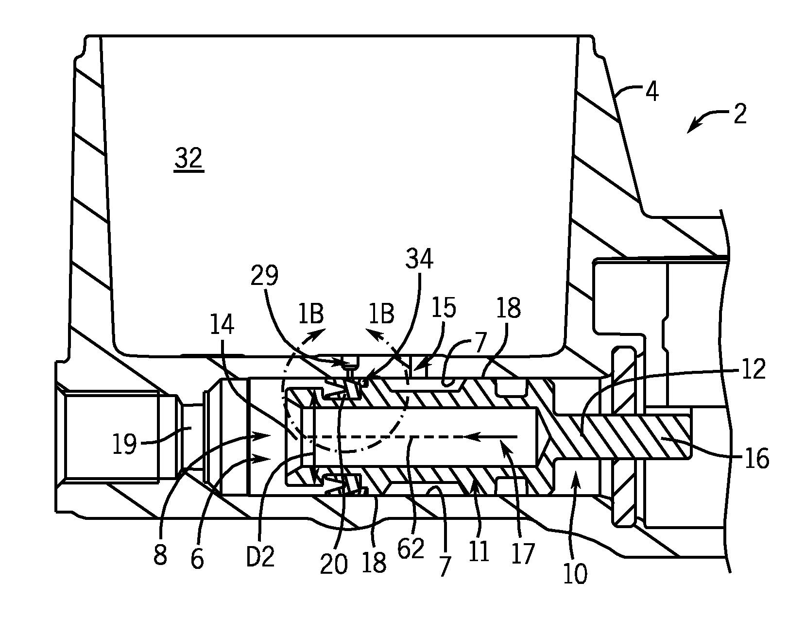
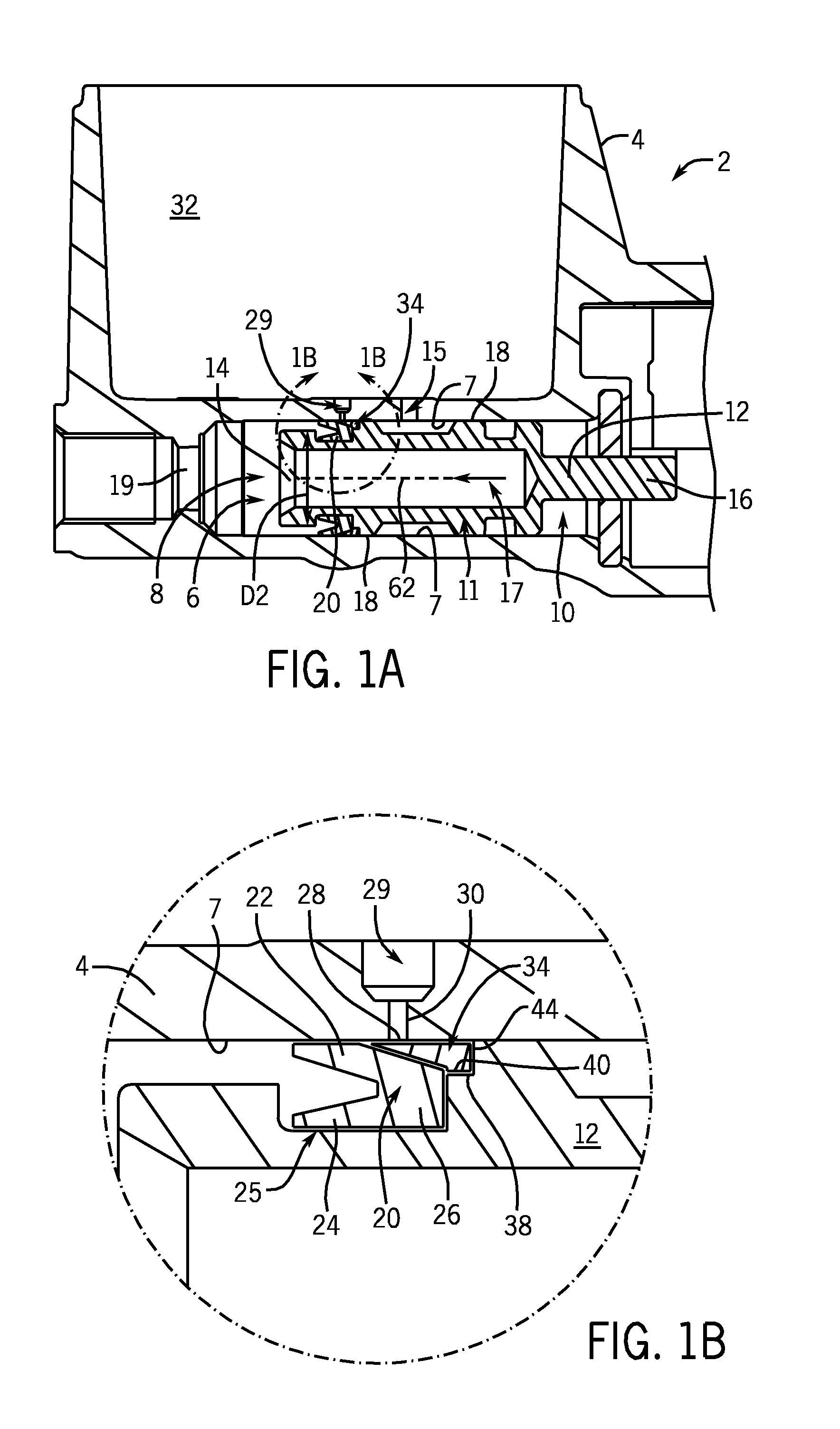
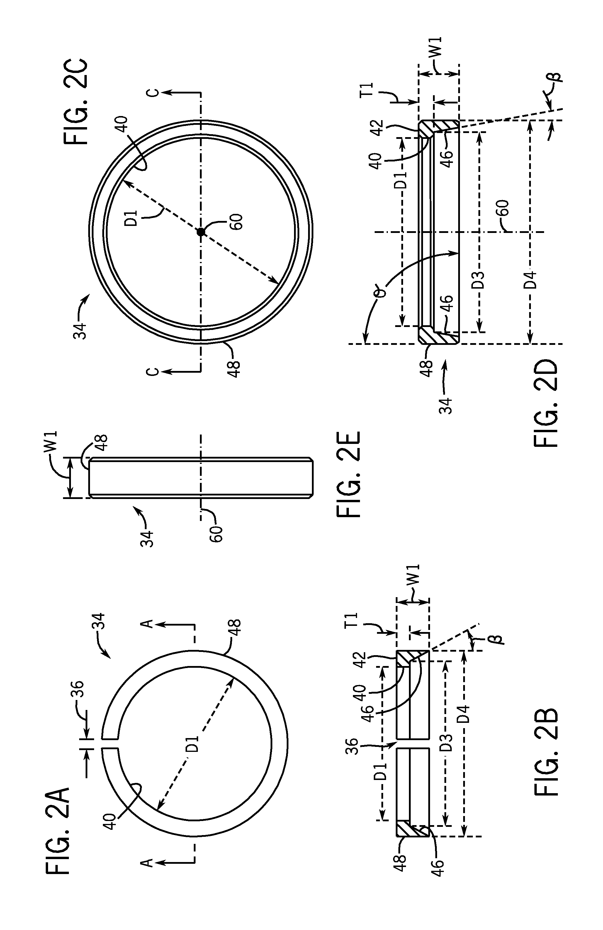
[0036]Referring to FIGS. 1A and 1B, a cross-sectional side view of a portion of an exemplary hydraulic master cylinder assembly 2 is depicted in FIG. 1A that includes a body portion 4. The master cylinder assembly 2 can be part of a braking system for one or more of a variety of land-based vehicles, such as a motorcycle, automobile, snowmobile, All Terrain Vehicle (ATV), Utility Terrain Vehicle (UTV), motorized and non-motorized bicycles, etc. In the present embodiment, the master cylinder assembly 2 is provided for use with an Anti-Lock Braking System (ABS) for use with one or more of such land vehicles. The body portion 4 houses a piston bore 6 having a bore wall 7, a first bore end 8, and a second bore end 10. Although the body portion 4 can he an integral structure, it is contemplated that it can include two or more components secured together.

[0037]The master assembly 2 further includes a piston assembly 11 having a piston 12 positioned in the bore 6, the piston having a first ...


PUM


Abstract

Disclosed herein is a hydraulic master cylinder body having a bore defined at least in part by a bore wall, wherein the bore wall includes an opening for hydraulic fluid to be passed into the bore, and a piston assembly situated at least substantially in the bore, the assembly having a piston with a piston body and at least one cup seal situated substantially around the piston body, the cup seal situated adjacent to the bore wall so as to be in sealing engagement therewith, and a back-up ring that is situated about the piston body, wherein the back-up ring is positioned to at least partially cover a portion of the cup seal that is adjacent to the bore wall and to prevent at least a portion of the cup seal from contacting the bore wall and the opening for hydraulic fluid during piston actuation.

Description

GROSS-REFERENCE TO RELATED APPLICATIONS[0001]This application claims the benefit of U.S. provisional patent application No. 61 / 392,140, which was filed on Oct. 12, 2010 and entitled “Hydraulic Brake Master Cylinder with Back-Up Ring,” and which is hereby incorporated by reference herein.FIELD OF THE INVENTION[0002]The hydraulic master cylinder with back-up ring relates generally to hydraulic brake master cylinders, and more particularly to piston sealing configurations in hydraulic brake master cylinders.BACKGROUND OF THE INVENTION[0003]Hydraulic brake systems are subjected to pressure created when brakes are applied. More particularly, applying pressure to the brake pedal of a braking system creates pressure in the master cylinder piston bore. In a traditional hydraulic braking system, the pressure created in the master cylinder piston bore is typically generated by a metal or plastic piston sealed by rubber cup seals, such as primary and secondary cup seals.[0004]In higher pressur...

Claims


Application Information

Patent Timeline
Patent Type & Authority Applications(United States)
IPC IPC(8): B60T11/16
CPCB60T11/22B60T11/236B60T11/232B60T11/165B62L3/023F16D65/28B60T11/16
Inventor GOHR, JEFFREY S.AHOLA, VESADIMSEY, JAMES
Owner PERFORMANCE SYST
Learn More