
Fast Cool Down Cryogenic Refrigerator

a cryogenic refrigerator and fast cooling technology, applied in the field of fast cooling down cryogenic refrigerators, can solve the problem of limiting the range over which the speed can be varied without incurring significant losses, and achieve the effect of maximizing the refrigeration rate and constant supply pressure at the compressor

Active Publication Date: 2012-04-12
SUMITOMO SHI CRYOGENICS OF AMERICA
View PDF8 Cites 37 Cited by
  • Summary
  • Abstract
  • Description
  • Claims
  • Application Information

AI Technical Summary

Benefits of technology

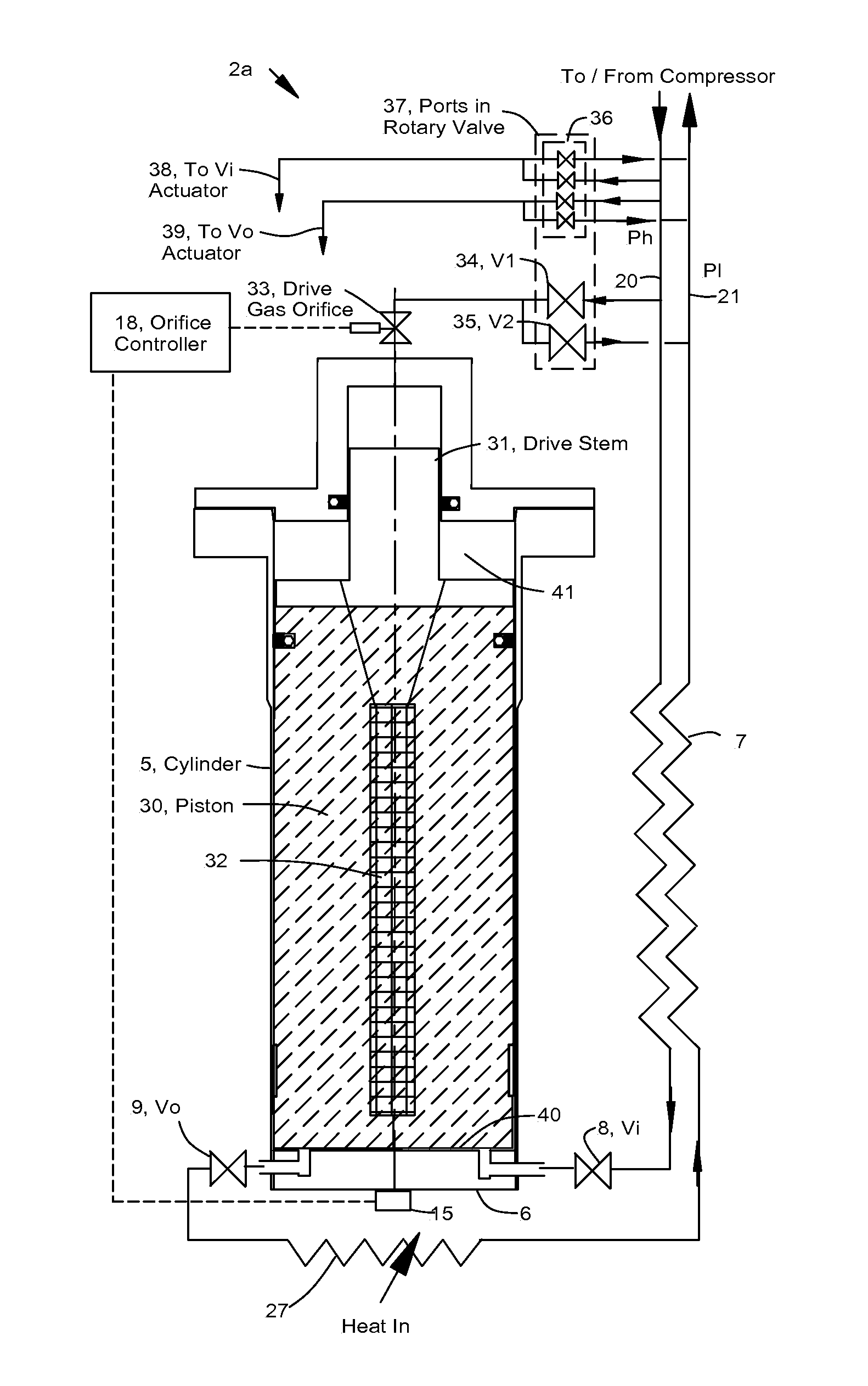
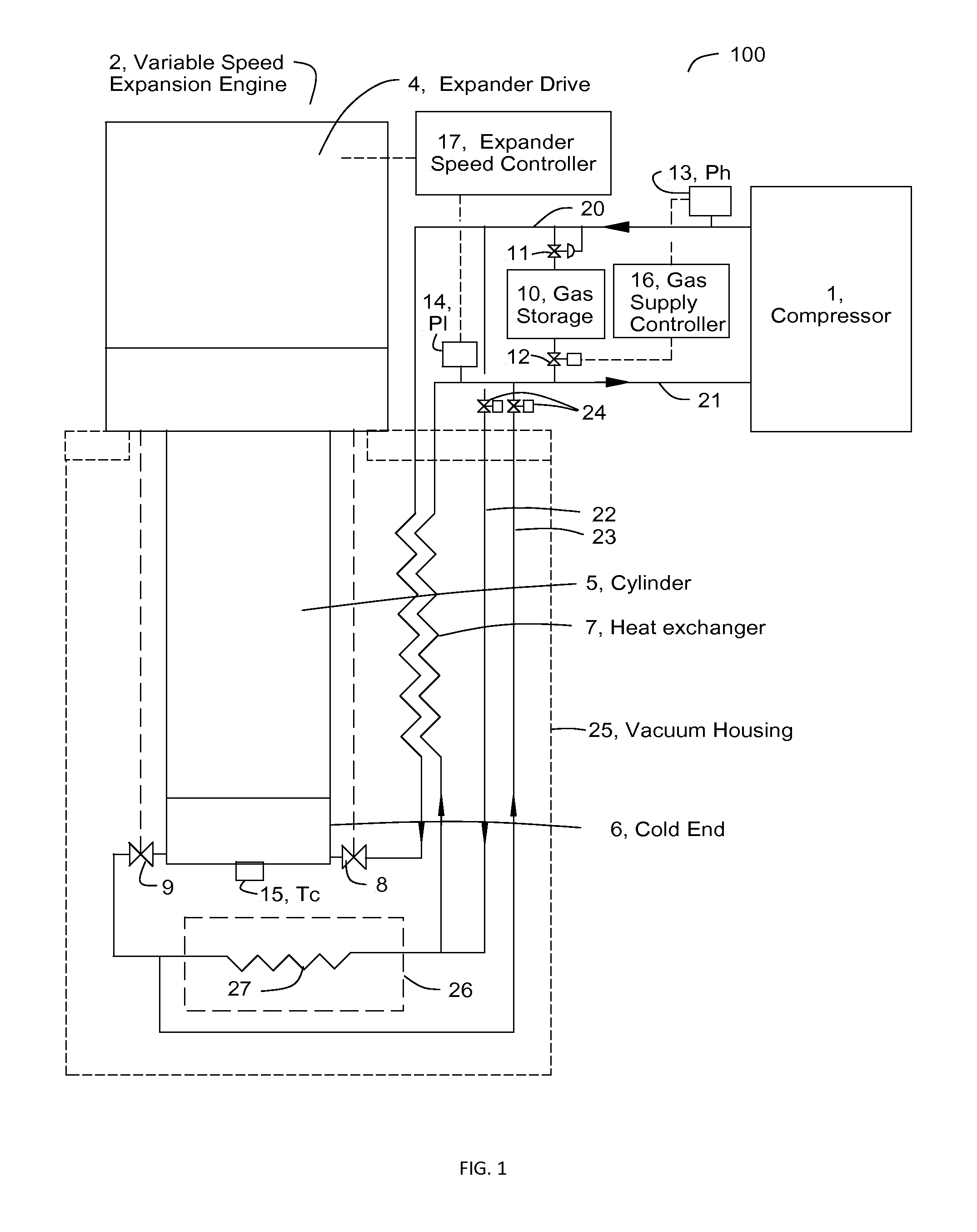
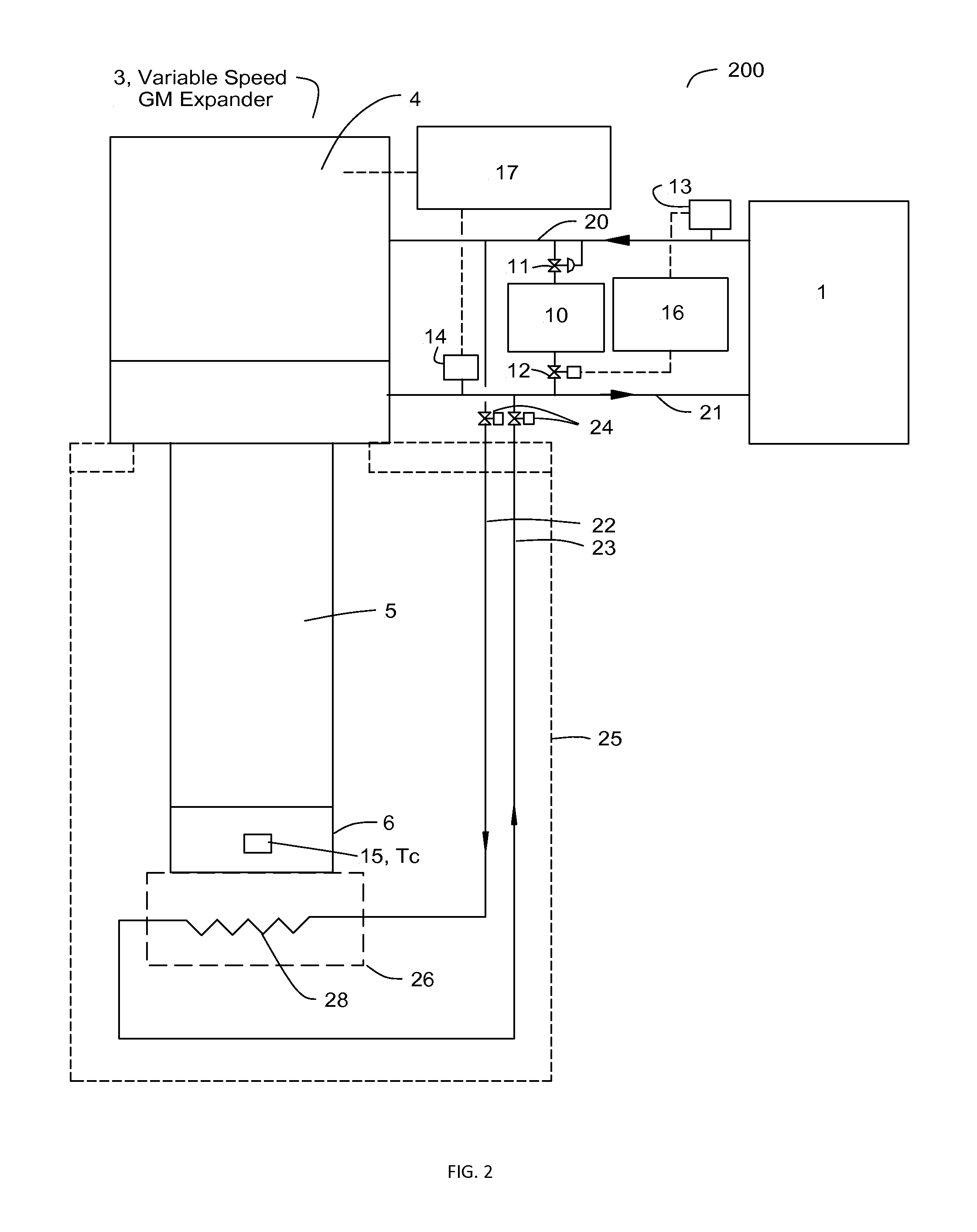
[0011]The present invention uses the full output power of the compressor during cool down to a cryogenic temperature to maximize the refrigeration rate by a) operating an expander at maximum speed near room temperature then slowing it down as the load is cooled, and b) transferring gas from a storage tank to the system in order to maintain a constant supply pressure at the compressor. An expansion engine or a GM expander, for example, is designed to operate at a speed of about 9 Hz at 300 K dropping to almost 1 Hz at 40 K and to operate at speeds that maintain a near constant pressure difference between the supply and return gas pressures at the compressor. The expanders can have a mechanical drive with a variable speed motor or a pneumatic drive with a variable speed motor tuning a rotary valve and having an adjustable orifice to optimize the piston or displacer speed as the expander speed changes.

Problems solved by technology

The problem of cooling a mass down to cryogenic temperatures is different than the problem of removing heat from a mass that is cold and is subject to heat loads from conduction, radiation, and internal heat generation.
This limits the range over which the speed can be varied without incurring significant losses.

Method used


Image

  • Fast Cool Down Cryogenic Refrigerator
  • Fast Cool Down Cryogenic Refrigerator
  • Fast Cool Down Cryogenic Refrigerator

Examples


Embodiment Construction

[0015]The embodiments of this invention that are shown in FIGS. 1, 2 and 3 use the same number and the same diagrammatic representation to identify equivalent parts.

[0016]For a system that operates on a Carnot cycle, no losses, the ideal refrigeration rate, Q, is equal to the power input, Pwr, by the relation

Q=Pwr*(Tc / (Ta−Tc))

where Ta is ambient temperature and Tc is the cold temperature at which the refrigeration is available. For a Brayton cycle system in which the gas is compressed and expanded adiabatically the relation is

Q=Pwr*(Tc / Ta)

[0017]From this it is seen that Q is maximized by operating the compressor at it the maximum power input that it is designed to handle. This is done by maintaining the high and low pressures, Ph and Pl, at constant values that maximize the input power. The mass flow rate from the compressor is constant. Most of this gas flows in and out of the expansion space, which is usually a fixed volume, thus as the expander cools down and the gas becomes dens...


PUM


Abstract

A refrigeration system for minimizing the cool down time of a mass to cryogenic temperatures including a compressor, an expander, a gas storage tank, interconnecting gas lines, and a control system. The compressor output is maintained near its maximum capability by maintaining near constant high and low pressures during cool down, gas being added or removed from the storage tank to maintain a near constant high pressure, and the speed of said expander being adjusted to maintain a near constant low pressure, no gas by-passing between high and low pressures.

Description

BACKGROUND OF THE INVENTION[0001]1. Field of the Invention[0002]This invention relates to a means to minimize the time to cool down a mass to cryogenic temperature using a refrigerator that operates on a Brayton or GM cycle.[0003]2. Background Information[0004]Most cryogenic refrigerators are designed to provide refrigeration at a low temperature over a long period, and system simplicity is given priority over efficiency during cool down. Most expanders and compressors are designed to operate at constant speed and most systems have a fixed charge of gas, usually helium. The mass flow rate through the expander is proportional to the density of the gas, thus when the expander is running warm it has a much lower flow rate than when it is cold. The compressor is sized to provide the flow rate that is needed when the unit is cold and the system is usually designed with an internal pressure relief valve that by-passes the excess flow of gas when it is warm. As the refrigerator cools down ...

Claims


Application Information

Patent Timeline
IPC IPC(8): F25B9/06F25B9/00
CPCF25B9/14F25B19/00F25B9/00
Inventor LONGSWORTH, RALPH
Owner SUMITOMO SHI CRYOGENICS OF AMERICA
Learn More