Infinitely variable transmission mechanism

a transmission mechanism and variable technology, applied in the direction of gears, transportation and packaging, other domestic objects, etc., to achieve the effect of reducing the space and weight requirements of a variable transmission drive system and reducing the gear requirements

Inactive Publication Date: 2012-04-12
COE THOMAS E
View PDF8 Cites 4 Cited by
  • Summary
  • Abstract
  • Description
  • Claims
  • Application Information

AI Technical Summary

Benefits of technology

[0007]An object of the present invention is to reduce the gears required within a variable transmission system while maintaining an appropriate range of active gear ratios.
[0008]Another object of the invention is to reduce the space and weight requirements of a variable transmission drive system.
[0009]Another object of the present invention is to provide automatic shifting of drive components within the transmission system to accommodate variable loading cycles.

Problems solved by technology

For slower speeds, sets of larger gears are required and for faster speeds sets of smaller gears are required with limiting factors being the cost, space and rate required to achieve appropriate gear ratio ranges for functional operation of the vehicle or other equipment.

Method used


Image

  • Infinitely variable transmission mechanism
  • Infinitely variable transmission mechanism
  • Infinitely variable transmission mechanism

Examples


Embodiment Construction

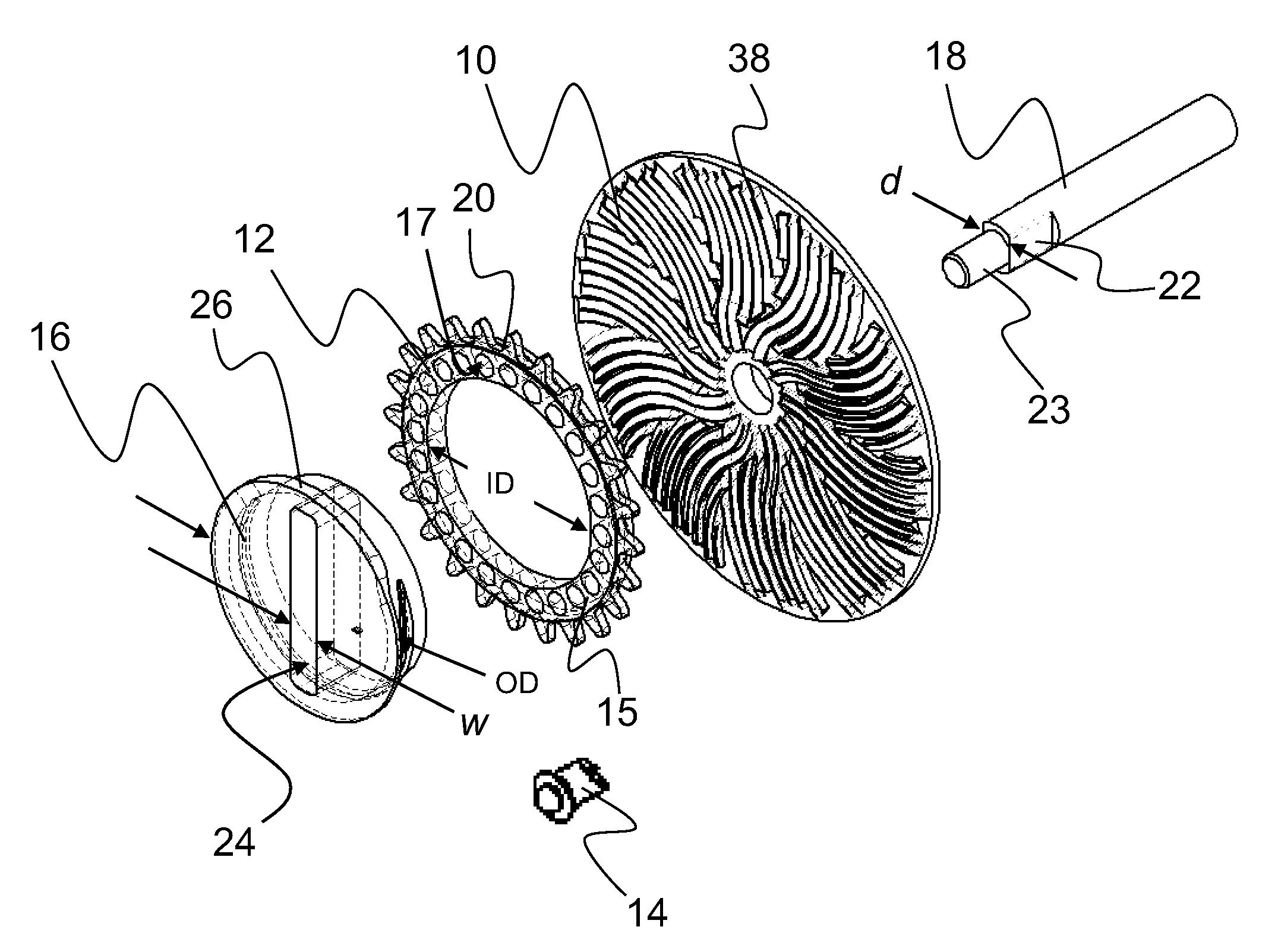
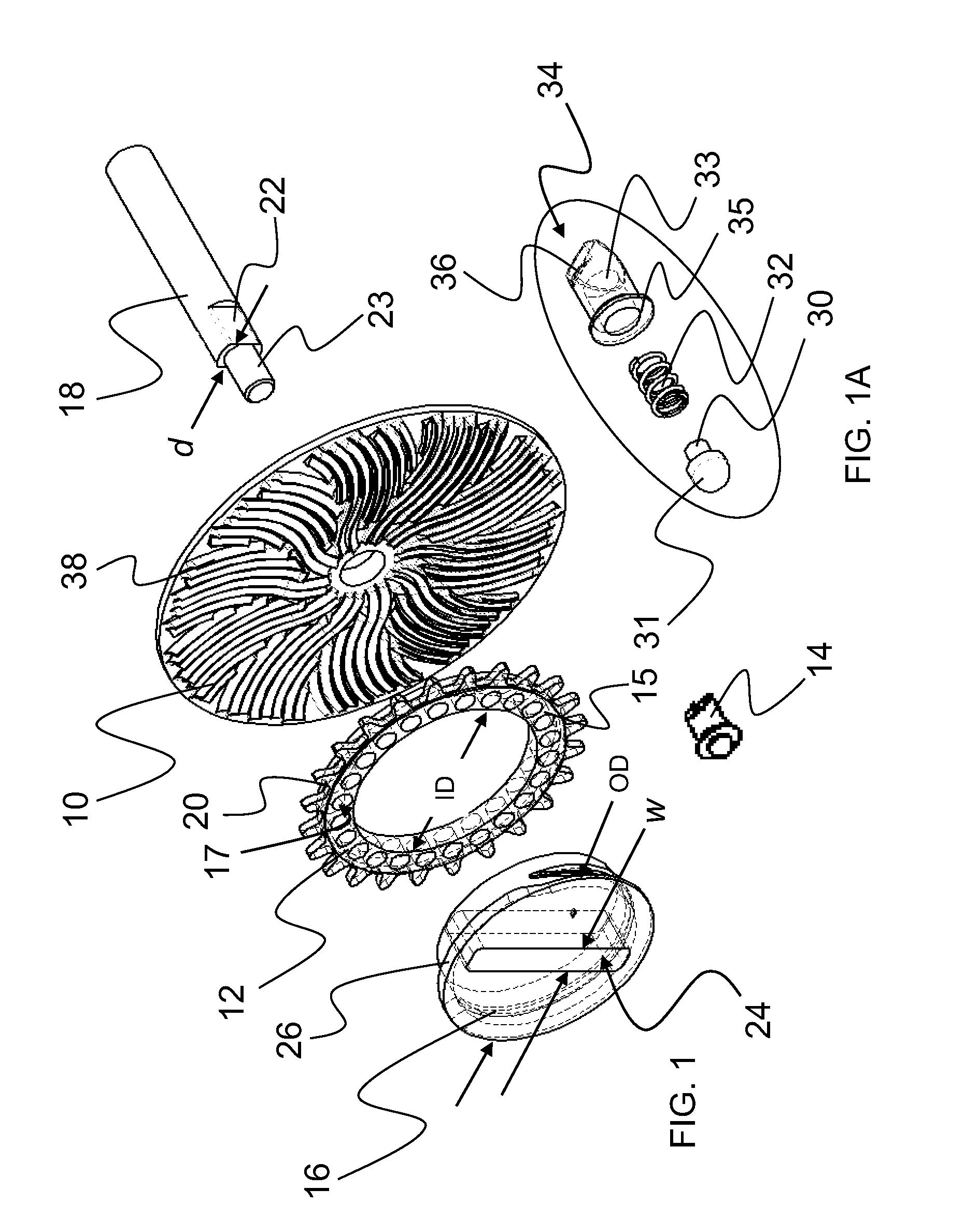
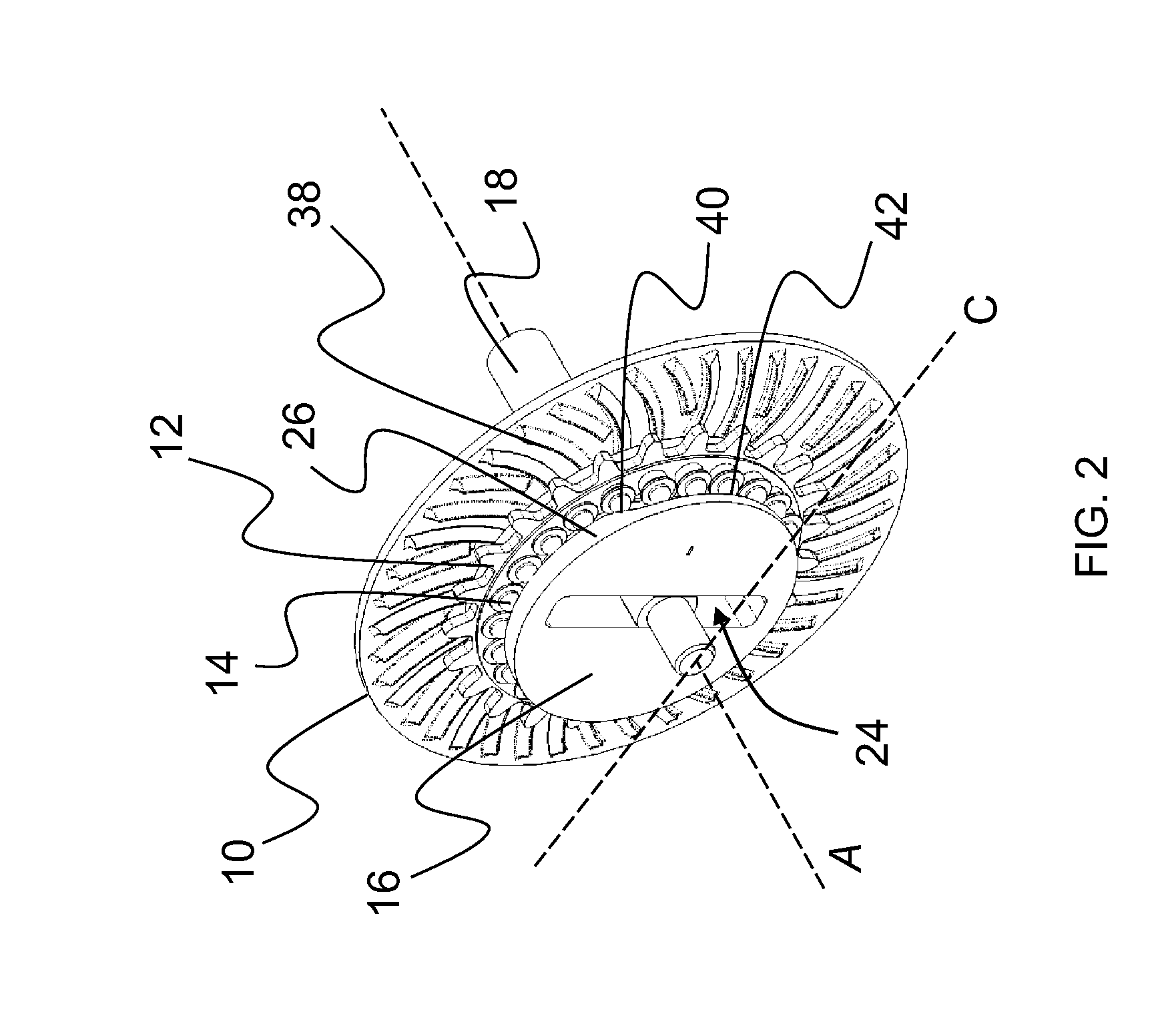
[0030]In its simplest form the infinitely variable transmission mechanism is made up of four major components; an array or channel plate 10, a drive ring 12, one or more pin-assemblies 14 and a movable position hub 16. All the components are in a compact sandwich arrangement. By simply moving the position hub 16 above or below the center line C of the array plate 10 the active gear ratio is changed with the output ratio being directly proportional to the distance moved. While positioned at dead center a 1:1 ratio is realized. When the position hub 16 is moved in a first direction, a speed reduction is induced, and when moved in an opposing direction, a speed increase occurs. This compact and simple arrangement can be applied to many types of equipment for example fishing reels, winches, bicycles, wheel chairs, generators, transport vehicles, and other machinery having rotating mechanisms.

[0031]As illustrated in FIG. 1, the four major components are mounted about a stationary axle 18...


PUM

PropertyMeasurementUnit
rotationaaaaaaaaaa
rotationaaaaaaaaaa
torqueaaaaaaaaaa

Abstract

An infinitely variable transmission mechanism that transmits produced torque to a wheel or output shaft without gears and is capable of an expansive range of active gear ratios in a relatively small envelope

Description

[0001]This application claims the benefit of U.S. provisional application No. 61 / 390,393 filed Oct. 6, 2010 and entitled Infinitely Variable Transmission Mechanism (Attorney Docket No. COETHO P04AUSPR), which is hereby incorporated herein by reference in its entirety.FIELD OF THE INVENTION[0002]The present invention relates to an infinitely variable transmission mechanism that transmits produced torque to a wheel or output shaft without gears and is capable of an expansive range of active gear ratios in a relatively small envelope.BACKGROUND OF THE INVENTION[0003]Mechanical gearing is used in almost any device having rotating parts, for example, bicycle gearing allows for a selection of an appropriate gear ratio for the speed and efficiency in varied physical terrains. An adjustment to the gear ratio adjusts the amount the bicycle moves forward on each pedal stroke. Based on the number of teeth on each sprocket gear of the bicycle, the smaller wheel gear rotates faster than the larg...

Claims


Application Information

Patent Timeline
Patent Type & Authority Applications(United States)
IPC IPC(8): F16H1/06B23P15/14
CPCF16H3/426Y10T74/19656Y10T29/49465
Inventor COE, THOMAS E.
Owner COE THOMAS E
Why Eureka
Try Eureka