Aircraft actuator hydraulic apparatus

Active Publication Date: 2012-04-12
NABLESCO CORP
View PDF26 Cites 10 Cited by
  • Summary
  • Abstract
  • Description
  • Claims
  • Application Information

AI Technical Summary

Benefits of technology

[0014]Also, the backup hydraulic pump, the electric motor, and the driver are installed inside the wing at which the elevator is installed, and are thus installed in a region closer to the actuator. Accordingly, there is no need for a long, large piping system or the like that is required when they are installed on the body side of the aircraft. This makes it possible to realize a reduction in size and weight of an aircraft actuator hydraulic apparatus (hereinafter, also referred to as a “hydraulic apparatus”). Further, in the hydraulic apparatus having this configuration, the cooling device for suppressing an increase in temperature of the apparatus is configured to simultaneously cool the backup hydraulic pump, the electric motor, and the driver. Accordingly, the backup hydraulic pump, the electric motor, and the driver can be efficiently cooled by the same cooling device. This makes it possible to suppress an inc

Problems solved by technology

However, this cooling device is configured as a mechanism that cools the electronic device by guiding the air outside the aircraft body to the electronic device an

Method used


Image

  • Aircraft actuator hydraulic apparatus
  • Aircraft actuator hydraulic apparatus
  • Aircraft actuator hydraulic apparatus

Examples


Example

First Embodiment

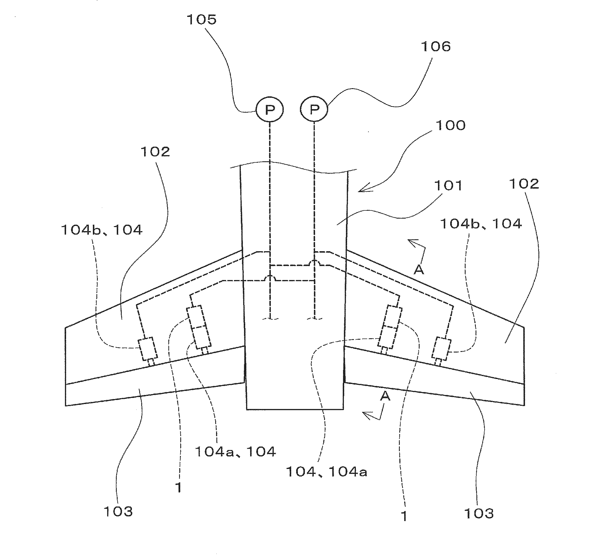
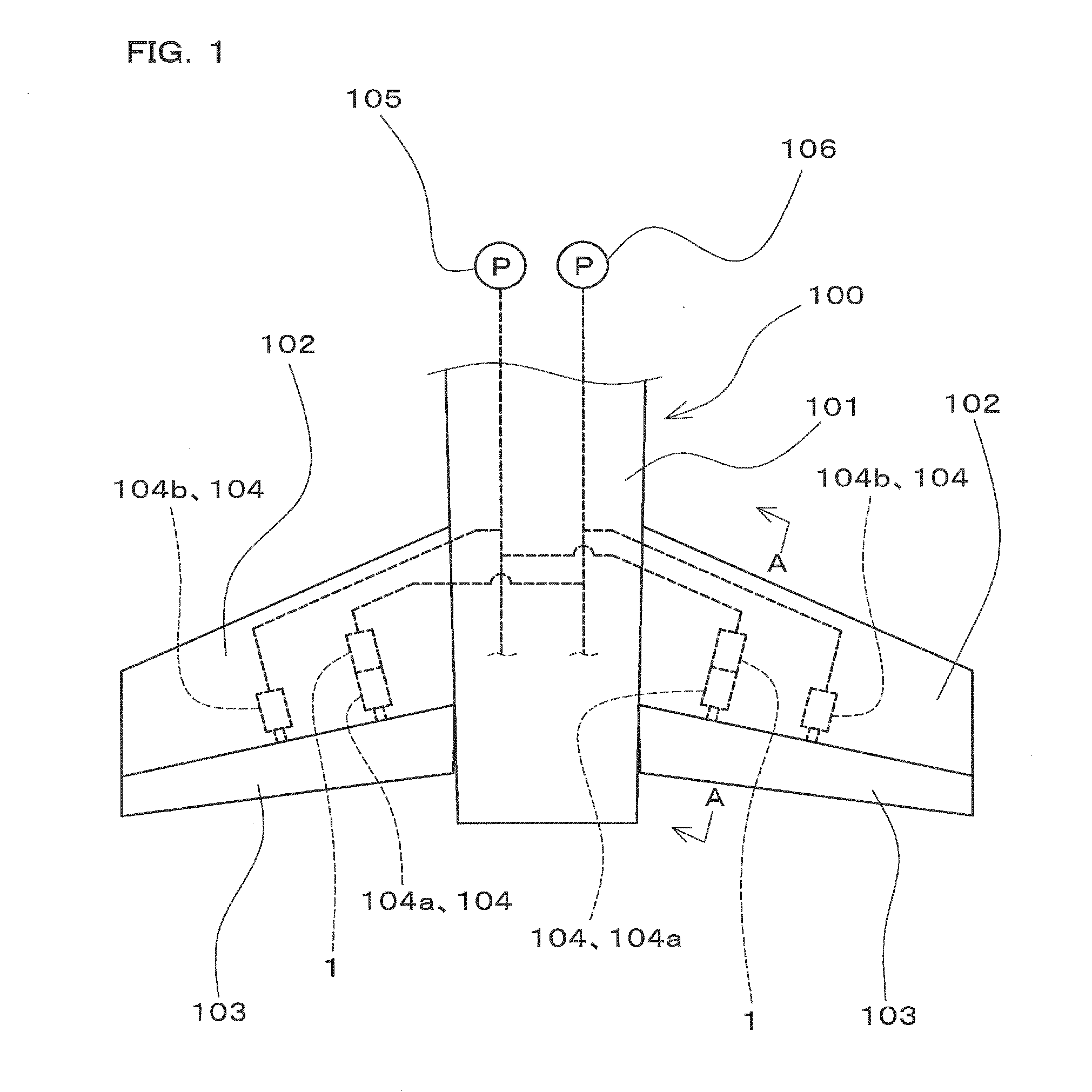
[0038]FIG. 1 is a diagram schematically showing part of an aircraft 100 to which an aircraft actuator hydraulic apparatus 1 (hereinafter, also simply referred to as a “hydraulic apparatus 1”) according to a first embodiment of the present invention is applied, showing a rear part of a body 101 of the aircraft 100 and a pair of tailplanes (102, 102). In FIG. 1, illustration of a vertical tail at the rear part of the body 101 is omitted.

[0039]Each of the two tailplanes (102, 102) is provided with an elevator 103 as a moving surface (flight control surface) constituting a control surface of the aircraft 100. The elevator 103 of each tailplane 102 is configured to be driven by a plurality of (for example, two) actuators 104 (104a, 104b), as illustrated in FIG. 1. Actuators (104a, 104b) for driving elevators 103 and a hydraulic apparatus 1 configured to supply pressure oil to one of the actuators, namely the actuator 104a, are installed inside each tailplane 102. Note tha...

Example

Second Embodiment

[0070]Next, an aircraft actuator hydraulic apparatus 2 (hereinafter, also simply referred to as a “hydraulic apparatus 2”) according to a second embodiment of the present invention will be described. As with the hydraulic apparatus 1 of the first embodiment, the hydraulic apparatus 2 is configured to supply pressure oil to a hydraulically operated actuator 104a for driving an elevator 103 that is provided at a tailplane 102 of an aircraft 100. Also, the hydraulic apparatus 2 is connected with a first aircraft central hydraulic power source 105, a reservoir circuit 110, and a control valve 109a as with the hydraulic apparatus 1 of the first embodiment. Further, the hydraulic apparatus 2 is configured to operate in accordance with a command signal from a flight controller 22 as with the hydraulic apparatus 1.

[0071]FIG. 5 is a diagram schematically showing, in a simplified manner, a hydraulic circuit including the hydraulic apparatus 2 together with the actuator 104a a...


PUM


Abstract

A hydraulic pump is installed inside a wing at which a control surface is provided, and supplies pressure oil to an actuator when a loss or degradation occurs in the function of aircraft central hydraulic power sources. An electric motor is installed inside the wing and drives the backup hydraulic pump. A driver is installed inside the wing and drives the electric motor. A cooling device is installed inside the wing and simultaneously cools the backup hydraulic pump, the electric motor, and the driver.

Description

CROSS-REFERENCE TO RELATED APPLICATIONS[0001]This application claims priority to Japanese Patent Application No. 2010-228357. The entire disclosure of Japanese Patent Application No. 2010-228357 is hereby incorporated herein by reference.BACKGROUND OF THE INVENTION[0002]1. Field of the Invention[0003]The present invention relates to an aircraft actuator hydraulic apparatus that supplies pressure oil to a hydraulically operated actuator for driving a control surface of an aircraft.[0004]2. Description of Related Art[0005]An aircraft is provided with control surfaces that are formed as moving surfaces (flight control surfaces) and are configured as an aileron, an elevator, and the like. Hydraulically operated actuators are often used as actuators for driving such control surfaces. Further, pressure oil is supplied to such an actuator from an aircraft central hydraulic power source. However, a loss or degradation of the function (pressure oil supply function) of the aircraft central hy...

Claims


Application Information

Patent Timeline
IPC IPC(8): B64C13/36
CPCY02T50/44B64C13/42Y02T50/40
Inventor NAKAGAWA, SHINGOFUKUI, ATSUSHI
Owner NABLESCO CORP
Why Eureka
Try Eureka