
Single photon detector and photon number resolving detector

Inactive Publication Date: 2012-04-12
ELECTRONICS & TELECOMM RES INST
View PDF1 Cites 11 Cited by
  • Summary
  • Abstract
  • Description
  • Claims
  • Application Information

AI Technical Summary

Benefits of technology

[0008]The present invention also provides a single photon detector and a photon number resolving detector, which decrease a probability that an after pulse is generated.
[0009]The present invention also provides a single photon detector and a photon number resolving detector, which have an enhanced photon count rate.
[0010]The present invention also provides a single photon detector and a photon number resolving detector, which decrease the influence on a waveform of a gate signal.
[0011]The present invention also provides a single photon detector and a photon number resolving detector, which enable the continuous change in a frequency of a gate signal.

Problems solved by technology

Such an effect is called an after-pulsing effect, which is one of important causes that raise an error in detecting a photon.
However, since typical photon detectors detect a relatively large avalanche, there are relatively many charge carriers that are left without being vanished.
Therefore, a dead time sufficient to remove the left charge carriers is required to be set long.

Method used


Image

  • Single photon detector and photon number resolving detector
  • Single photon detector and photon number resolving detector
  • Single photon detector and photon number resolving detector

Examples


first embodiment

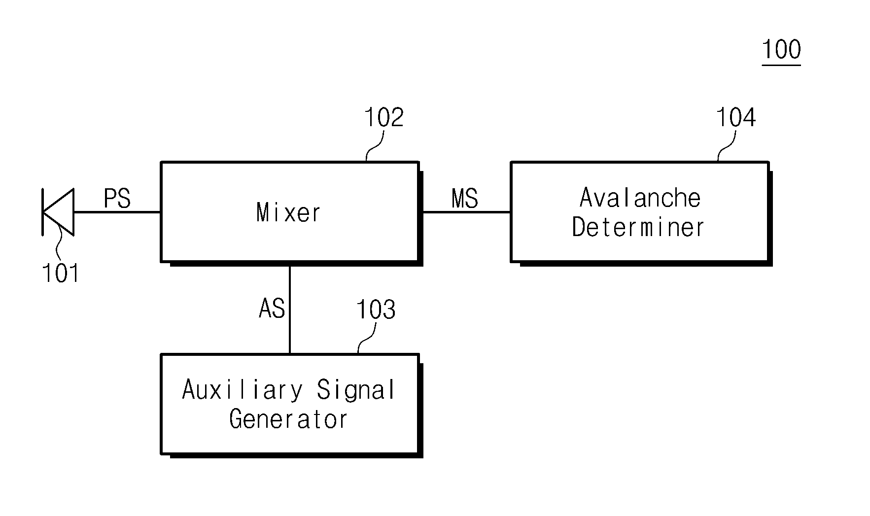
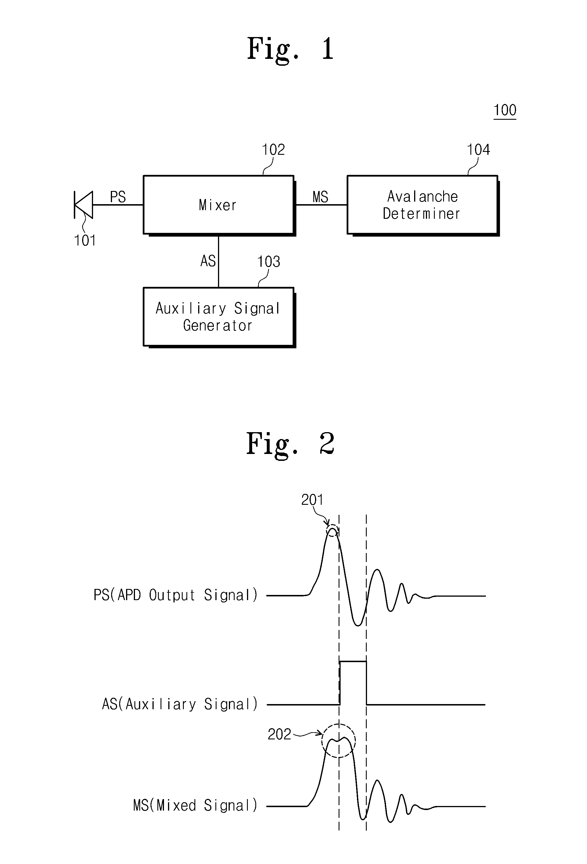
[0045]FIG. 1 is a diagram illustrating a single photon detector according to the present invention.

[0046]Referring to FIG. 1, a single photon detector 100 according to the first embodiment of the present invention includes an Avalanche Photo Diode (APD) 101, a mixer 102, an auxiliary signal generator 103, and an avalanche determiner 104.

[0047]The APD 101 includes a light receiving element that receives a photon to output an electric signal PS. The electric signal PS, which is outputted with the received photon, includes an avalanche signal. The APD 101 delivers the output signal PS to the mixer 102.

[0048]The auxiliary signal generator 103 generates an auxiliary signal AS for effectively detecting an avalanche signal with an amplitude less than the amplitude of a capacitive response of the APD 101, and delivers the generated auxiliary signal AS to the mixer 102.

[0049]The mixer 102 receives the output signal PS outputted from the APD 101 and the auxiliary signal AS outputted from the ...

second embodiment

[0063]FIG. 5 is a diagram illustrating a single photon detector 500 according to the present invention.

[0064]Referring to FIG. 5, the single photon detector 500 includes an APD 101, a mixer 102, an auxiliary signal generator 103, an avalanche determiner 104, and a gate signal generator 501.

[0065]The single photon detector 500 of FIG. 5 includes the single photon detector 100 of FIG. 1, and further includes the gate signal generator 501. The APD 101, mixer 102, auxiliary signal generator 103, and avalanche determiner 104, being elements other than the gate signal generator 501, are as described above with reference to FIG. 1, and thus their detailed description will not be provided below.

[0066]The APD 101 has low quantum efficiency and a high probability that an after pulse is generated, and thus is generally used in a gated Geiger mode.

[0067]The gate signal generator 501 generates a gate signal for operating the APD 101 in the gated Geiger mode, and delivers the generated gate signa...

third embodiment

[0069]FIG. 6 is a diagram illustrating a single photon detector 600 according to the present invention.

[0070]Referring to FIG. 6, the single photon detector 600 includes an APD 101, a mixer 102, an auxiliary signal generator 103, an avalanche determiner 104, a gate signal generator 501, and a time delayer 601.

[0071]The single photon detector 600 of FIG. 5 includes the single photon detector 500 of FIG. 5, and further includes the time delayer 601. The APD 101, mixer 102, auxiliary signal generator 103, avalanche determiner 104, and gate signal generator 501, being elements other than the time delayer 601, are as described above with reference to FIGS. 1 and 5, and thus their detailed description will not be provided below.

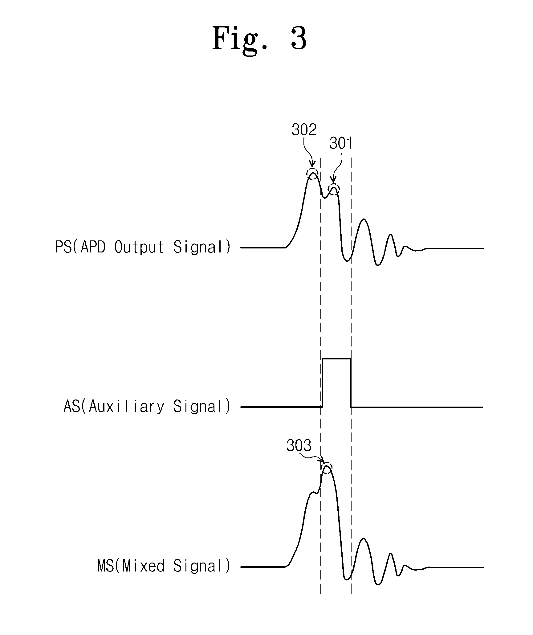
[0072]The mixer 102 receives the auxiliary signal AS and the output signal PS of the APD 101, and mixes the two signals AS and PS to output the mixed signal MS. It is more easy to determine whether an avalanche occurs when the amplitude of the mixed signal MS is th...


PUM


Abstract

Provided is a single photon detector and a photon number detector which use an APD and include an auxiliary signal generator, a light receiving element, a mixer, and a determiner The auxiliary signal generator generates an auxiliary signal. The light receiving element receives a photon to output an electric signal. The mixer receives and mixes an output signal of the light receiving element and the auxiliary signal. The determiner determines whether the photon is received or the number of received photons. The single photon detector and photon number resolving detector detect an avalanche of an amplitude less than the amplitude of a capacitive response. A probability that an after pulse is generated can be reduced. A photon count rate is enhanced. The influence on the waveform of the gate signal can be decreased. The frequency of the gate signal can be continuously changed.

Description

CROSS-REFERENCE TO RELATED APPLICATIONS[0001]This U.S. non-provisional patent application claims priority under 35 U.S.C. §119 of Korean Patent Application Nos. 10-2010-0097298, filed on Oct. 6, 2010, and 10-2011-0003146, filed on Jan. 12, 2011, the entire contents of which are hereby incorporated by reference.BACKGROUND OF THE INVENTION[0002]The present invention disclosed herein relates to a photon detector, and more particularly, to a single photon detector and a photon number resolving detector, which use an avalanche photo diode.[0003]With the advance of quantum encryption communication and information communication technologies, technology of detecting a photon is becoming increasingly more important. Particularly, an InGaAs / InP type of avalanche photo diode is mostly used in single photon detectors that are used in a telecommunication band such as 1.3 μm to 1.5 μm and detect an optical signal that is weak in intensity as in a single photon level. InGaAs / InP type of avalanche ...

Claims


Application Information

Patent Timeline
IPC IPC(8): H01L31/107H01L31/08
CPCG01J1/44
Inventor CHO, SEOK-BEOMNOH, TAE-GON
Owner ELECTRONICS & TELECOMM RES INST
Learn More