

System and Method for Calibrating Backlight Devices
a backlight device and backlight technology, applied in the field of electronic display sensor systems, can solve the problems of limited temperature and/or amount of direct sunlight, limited display visibility, and limited use of advanced electronic display systems, and achieve the effect of improving system accuracy
- Summary
- Abstract
- Description
- Claims
- Application Information
AI Technical Summary
Benefits of technology
Problems solved by technology
Method used
Image

Examples
Embodiment Construction
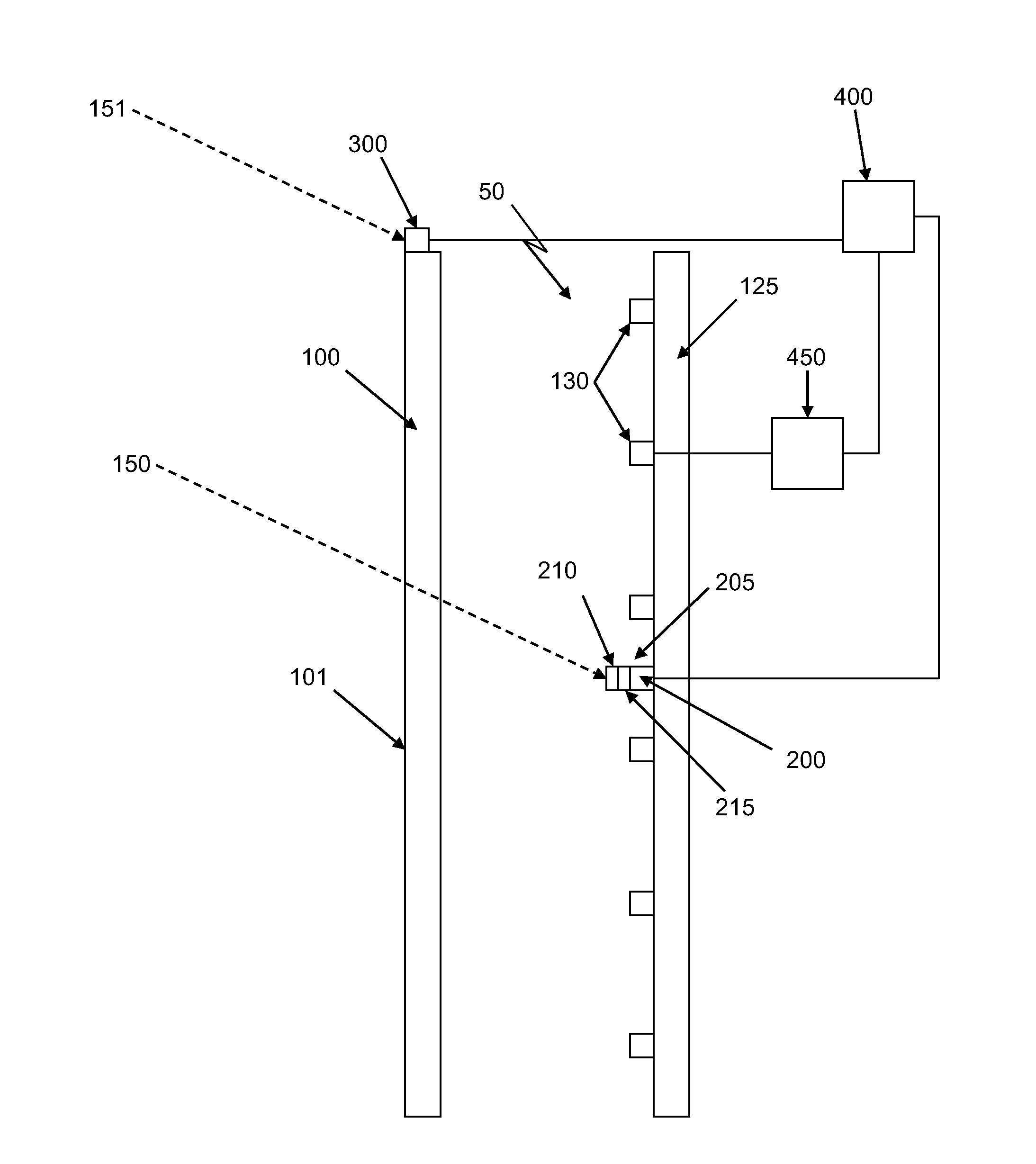
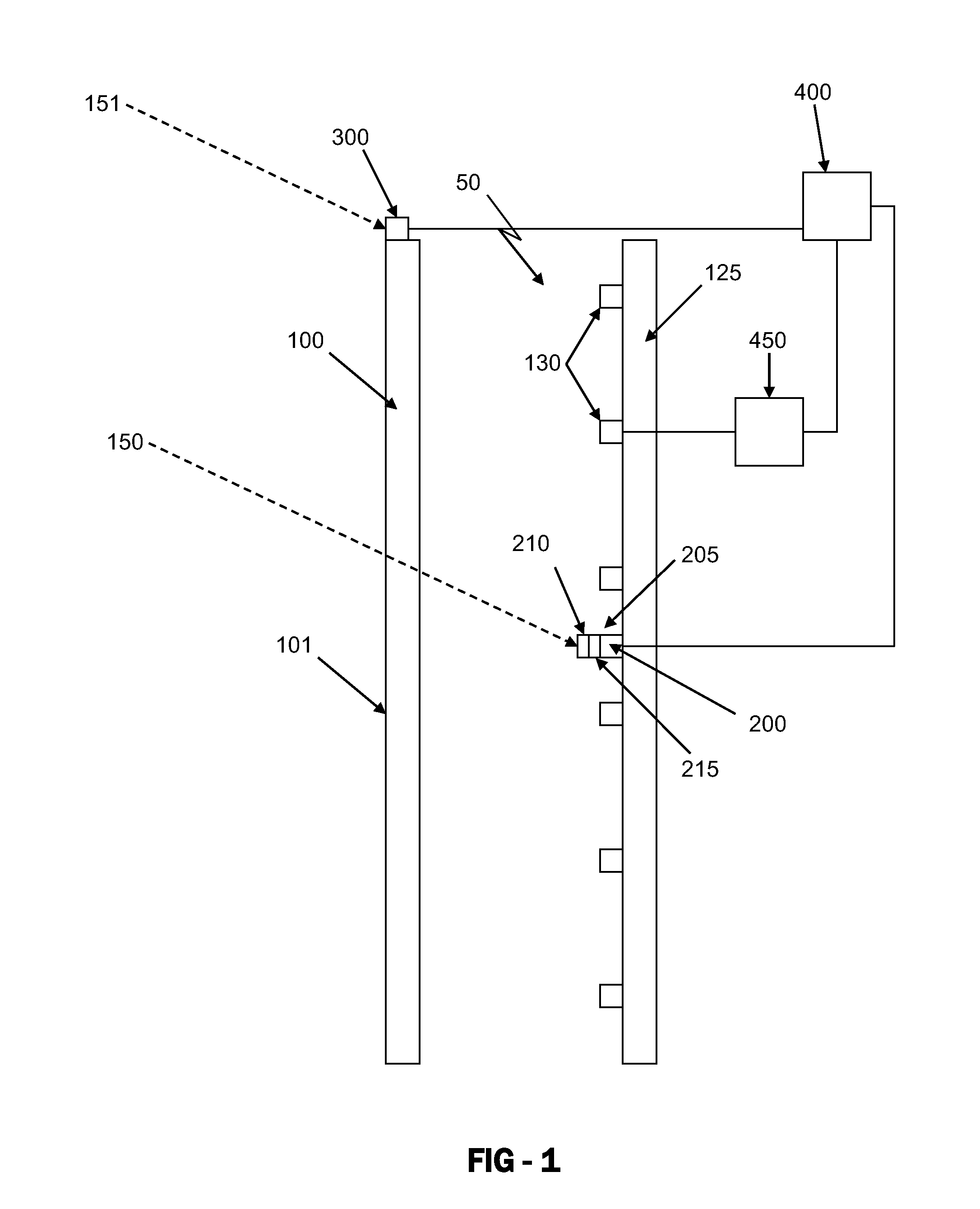
[0007]Exemplary embodiments include a system and method for calibrating and / or adjusting the backlight levels for a display based on light sensor data. An exemplary system contains a light sensor assembly within the backlight cavity of the display as well as a light sensor assembly placed to detect the ambient light levels. The sensors as well as the circuit for powering the backlight assembly may be calibrated to improve the accuracy of the system.
[0008]Some sources of backlighting degrade over time. For example, LED's may degrade over time and emit less light. Exemplary embodiments also allow for the brightness of a display to adjust based on the degradation of the light source.
[0009]Also for indoor applications, the temperature that an electronic display is subjected to will also vary only a small amount. Typically, these displays only see a range of temperatures near room temperature (ex. 65-75 degrees Fahrenheit). However, for outdoor applications, displays will see a very wide...
PUM
 Abstract
Description
Claims
Application Information