Switched mode voltage regulator and method of operation

a voltage regulator and switch mode technology, applied in the field of switches, can solve the problems of long-term reliability problems, fast ramp rate, and reset before power-up completion

Active Publication Date: 2012-04-12
NXP USA INC
View PDF12 Cites 26 Cited by
  • Summary
  • Abstract
  • Description
  • Claims
  • Application Information

AI Technical Summary

Problems solved by technology

However, upon power-up, these power supplies may have very fast ramp rate or may overshoot which may cause various problems.
For example, the very fast ramp rate may trigger centralized electrostatic discharge (ESD) protection, which may result in a reset before completion of the power-up.
The overshoot may result in an over voltage condition which may cause long term reliability problems.

Method used


Image

  • Switched mode voltage regulator and method of operation
  • Switched mode voltage regulator and method of operation
  • Switched mode voltage regulator and method of operation

Examples


Embodiment Construction

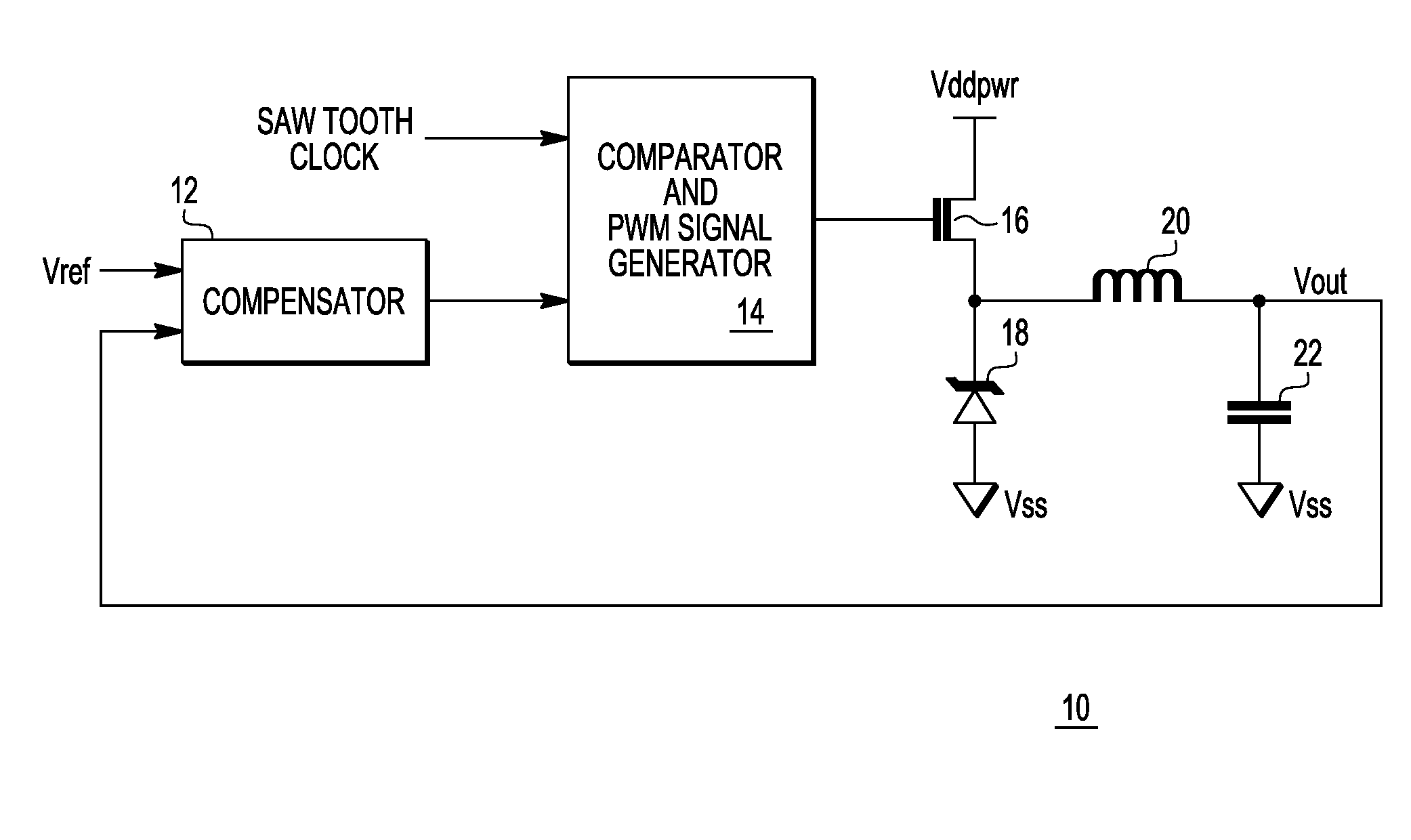
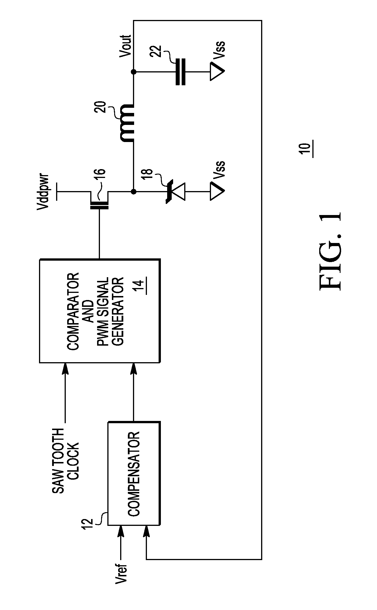
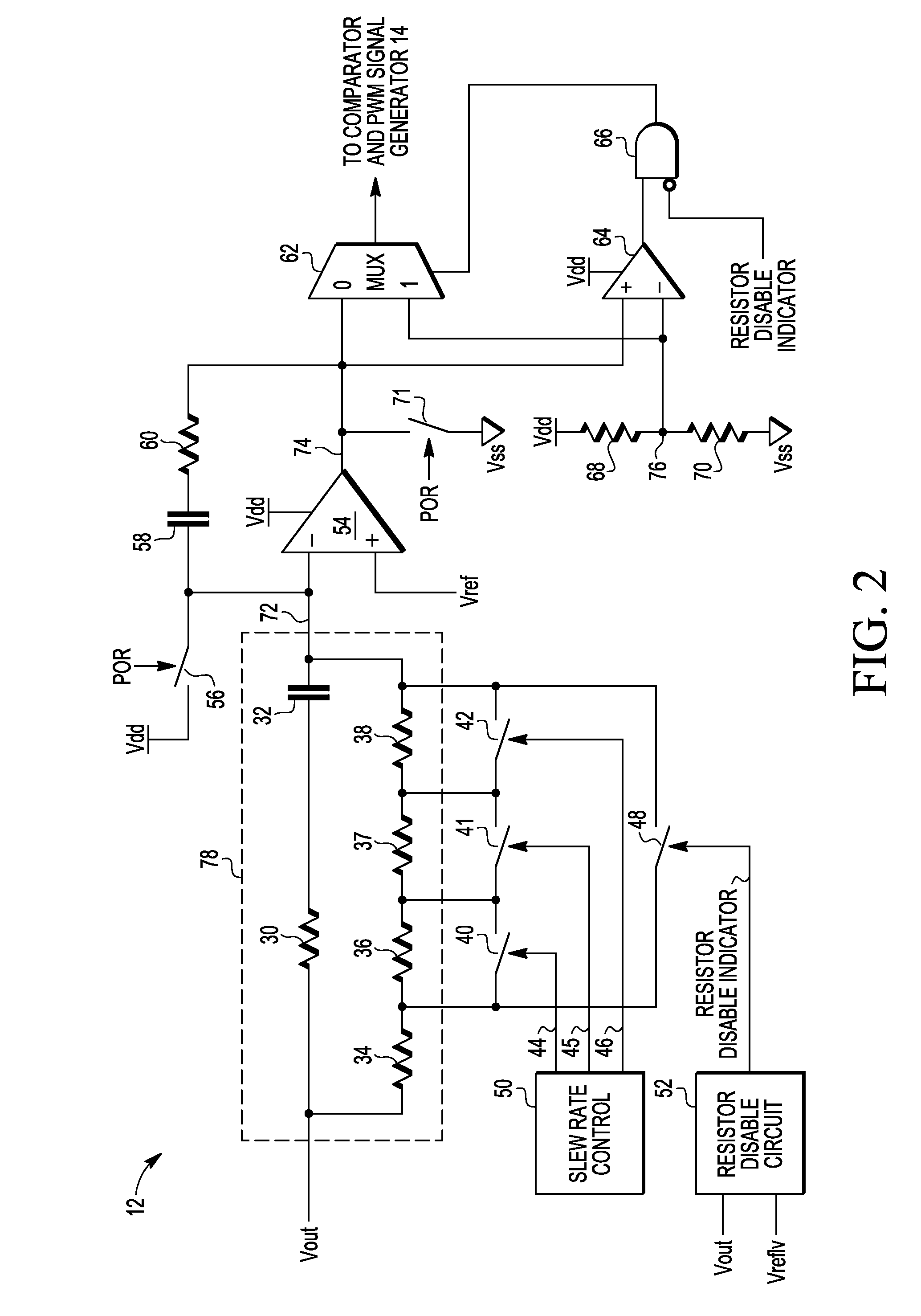
[0008]In one embodiment, a switched mode voltage regulator includes a compensator which provides an output for comparison with a saw tooth clock. The result of this comparison is used to generate a pulse width modulated (PWM) signal for controlling a transistor which regulates an output voltage of the voltage regulator. In one embodiment, the compensator uses the output voltage and a reference voltage to provide an integration error as its output. The compensator applies a filter having a resistor-capacitor (RC) time constant to the output voltage prior to comparison with the reference voltage. In one embodiment, the RC time constant has a particular value during normal operation, but an increased value during start-up of the voltage regulator. The increased value of the RC time constant allows for a slower ramp up of the integration error as compared to the ramp up which would occur with the RC time constant allowed during normal operation. In this manner, the duty cycle of the PWM...


PUM


Abstract

A voltage regulator includes a transistor, a comparator, and a compensation circuit. The comparator has a first input terminal coupled to receive a clock signal, a second input terminal, and an output terminal coupled to a control electrode of the transistor. The compensation circuit has a first input terminal coupled to receive a reference voltage, a second input terminal coupled to the output terminal of the voltage regulator, and an output terminal coupled to the second input terminal of the comparator. The compensation circuit has a filter circuit. The filter circuit has a first RC time constant during startup of the voltage regulator, and the filter circuit has a second RC time constant during normal operation. Changing the RC time constant for startup prevents an overshoot of an output voltage of the voltage regulator.

Description

BACKGROUND[0001]1. Field[0002]This disclosure relates generally to regulators, and more specifically, to a switched mode voltage regulator.[0003]2. Related Art[0004]Switched mode voltage regulators are commonly used as power supplies. However, upon power-up, these power supplies may have very fast ramp rate or may overshoot which may cause various problems. For example, the very fast ramp rate may trigger centralized electrostatic discharge (ESD) protection, which may result in a reset before completion of the power-up. The overshoot may result in an over voltage condition which may cause long term reliability problems. Therefore, a need exists for a switched mode voltage regulator with improved overshoot and ramp rate control.BRIEF DESCRIPTION OF THE DRAWINGS[0005]The present invention is illustrated by way of example and is not limited by the accompanying figures, in which like references indicate similar elements. Elements in the figures are illustrated for simplicity and clarity...

Claims


Application Information

Patent Timeline
Patent Type & Authority Applications(United States)
IPC IPC(8): G05F1/618
CPCH02M1/36
Inventor DAO, CHRIS C.PIETRI, STEFANOREN, JUXIANG
Owner NXP USA INC
Why Eureka
Try Eureka