Electromagnetic operator for an electrical contactor and method for controlling same

a technology of electrical contactor and operator, which is applied in the direction of circuit-breaking switches, circuit-breaking switches for excess current, electromagnetic relay details, etc., can solve the problems of reducing the energizing effect of the pickup coil, and increasing the cost of the devi

Inactive Publication Date: 2001-05-15
ALLEN-BRADLEY CO LLC
View PDF2 Cites 25 Cited by
  • Summary
  • Abstract
  • Description
  • Claims
  • Application Information

AI Technical Summary

Problems solved by technology

When the actuating current is removed, biasing members return the movable assembly back to its normal position thus breaking the electrical connection or opening the electrical circuit.
However, advantages and disadvantages are associated with each type of assembly.
However, if the time or force varies, as is sometimes the case, such arrangements may either provide insufficient or excessive periods of energization of the pickup coil.
In addition to the foregoing drawbacks, where conventional

Method used


Image

  • Electromagnetic operator for an electrical contactor and method for controlling same
  • Electromagnetic operator for an electrical contactor and method for controlling same
  • Electromagnetic operator for an electrical contactor and method for controlling same

Examples


Embodiment Construction

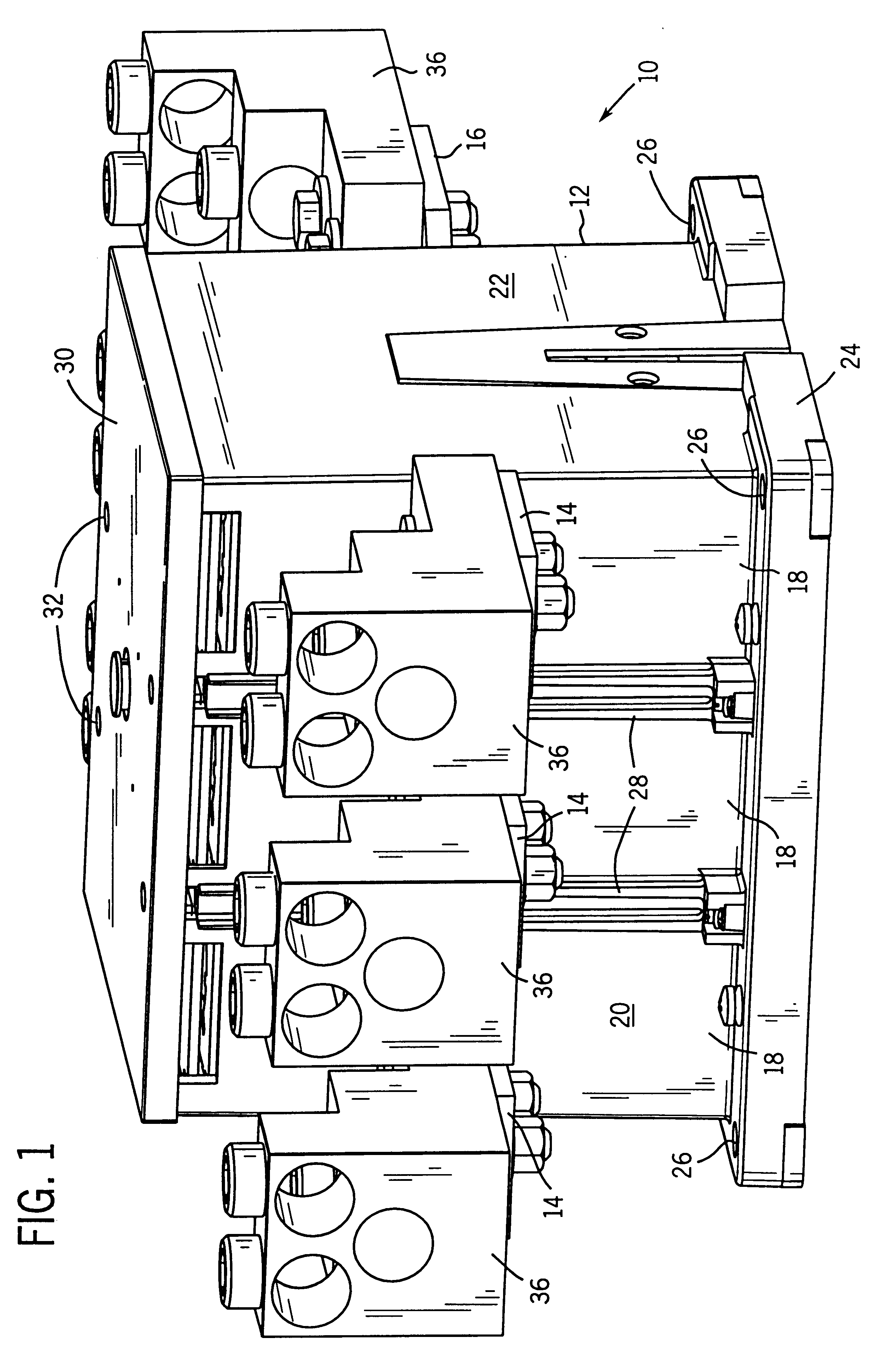
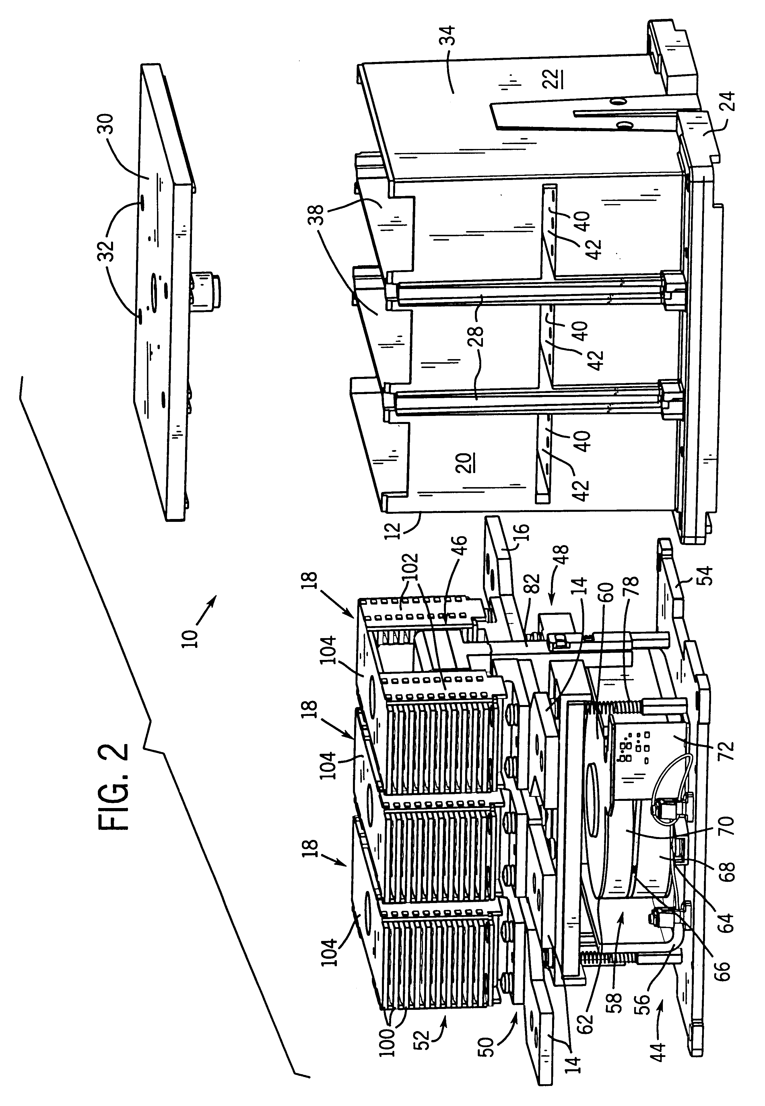
Turning now to the drawings, and referring first to FIG. 1, an electrical contactor 10 is illustrated in the form of a three-phase contactor for completing electrical current carrying paths for three separate phases of electrical power. Contactor 10 includes a housing 12 from which input or line terminals 14 and output or load terminals 16 extend. Contactor 10 is divided into three separate phase sections 18, with a pair of input and output terminals being associated with each phase section. Housing 12 includes end panels 20 and side walls 22 enclosing internal components as described more fully below. Input and output terminals 14 and 16 extend from end panels 20 for connection to power supply and load circuitry. Housing 12 further includes a lower securement flange 24 having apertures 26 formed therein for securing the contactor to a support base, such as in a conventional industrial enclosure (not shown). Ribs 28 are formed on end panels 20 to aid in electrically isolating phase ...


PUM


Abstract

An electromagnetic operator includes first and second coils wound coaxially An armature partially surrounds the coils for channeling flux during energization of the coils. The armature may be formed of a bent plate and secured to a ferromagnetic support. A control circuit applies energizing signals to the coils during operation. Both coils are energized during an initial phase of operation. One of the coils is subsequently released or de-energized automatically. A timing circuit removes current from the second coil after a variable time period. The time period may be a function of the configuration of the timing circuit, such as an RC time constant, and of the energizing signal.

Description

1. Field of the InventionThe present invention relates to electrical contactors and similar devices for completing and interrupting electrical current-carrying paths between a source of electrical energy and a load. More particularly, the invention relates to a coil assembly and actuator for such a device which facilitates assembly and installation, and which provides improved electrical, magnetic and thermal performance during transient and steady state phases of operation.2. Description Of The Related ArtA great variety of devices have been designed for completing and interrupting current-carrying paths between an electrical source and an electrical load. In one type of device, commonly referred to as a contactor, a set of movable contacts is displaced relative to a set of stationary contacts, so as to selectively complete a conductive path between the stationary contacts. In remote-controllable contactors of this type, an actuating assembly is provided to cause the movable contac...

Claims


Application Information

Patent Timeline
IPC IPC(8): H01H50/54H01H50/00H01H47/08H01H47/00H01H50/44
CPCH01H50/30H01H50/546H01H47/08H01H50/44
Inventor KAPPEL, MARK A.WALTZ, RICHARD W.SMITH, RICHARD G.SWIETLIK, DONALD F.HANNULA, RAYMOND H.WIELOCH, CHRISTOPHER J.ANNIS, JEFFREY R.
Owner ALLEN-BRADLEY CO LLC
Why Eureka
Try Eureka