
Reference symbol structure for dft spread OFDM system

a reference symbol and channel estimation technology, applied in the field of mobile communications, can solve the problems of reducing the data transmission rate, difficult to expect satisfactory performance of the reference symbol structure in the lte system, and difficulty in satisfying the reference symbol structure based on the lte system, so as to minimize the increase of the overhead and minimize the effect of the increase of the papr

Active Publication Date: 2012-04-12
ELECTRONICS & TELECOMM RES INST
View PDF10 Cites 58 Cited by
  • Summary
  • Abstract
  • Description
  • Claims
  • Application Information

AI Technical Summary

Benefits of technology

[0009]An aspect of the present invention is to temporally frequently transmit a reference symbol without increasing an overhead.
[0010]An aspect of the present invention is to multiplex a data symbol and a reference symbol in the same OFDM symbol while minimizing an increase in a PAPR.Technical Solutions
[0013]According to an aspect of the present invention, a reference symbol may be transmitted temporally and frequently without increasing an overhead.
[0014]According to an aspect of the present invention, a data symbol and a reference symbol may be multiplexed in the same OFDM symbol while minimizing an increase in a PAPR.

Problems solved by technology

However, a reference symbol structure based on an LTE system has difficulty in satisfying this.
Therefore, it is difficult to expect a satisfactory performance with the reference symbol structure in the LTE system.
However, while an improvement in a performance of the channel estimation is ensured, an overhead increase due to the reference symbols may lead to a decrease in a data transmission rate.
In this case, an overhead due to a cyclic prefix may increase, interference between data and a reference symbol in a data reception apparatus may increase, and the channel estimation may be complex.

Method used


Image

  • Reference symbol structure for dft spread OFDM system
  • Reference symbol structure for dft spread OFDM system
  • Reference symbol structure for dft spread OFDM system

Examples


Embodiment Construction

[0021]Reference will now be made in detail to embodiments of the present invention, examples of which are illustrated in the accompanying drawings, wherein like reference numerals refer to the like elements throughout. The embodiments are described below in order to explain the present invention by referring to the figures.

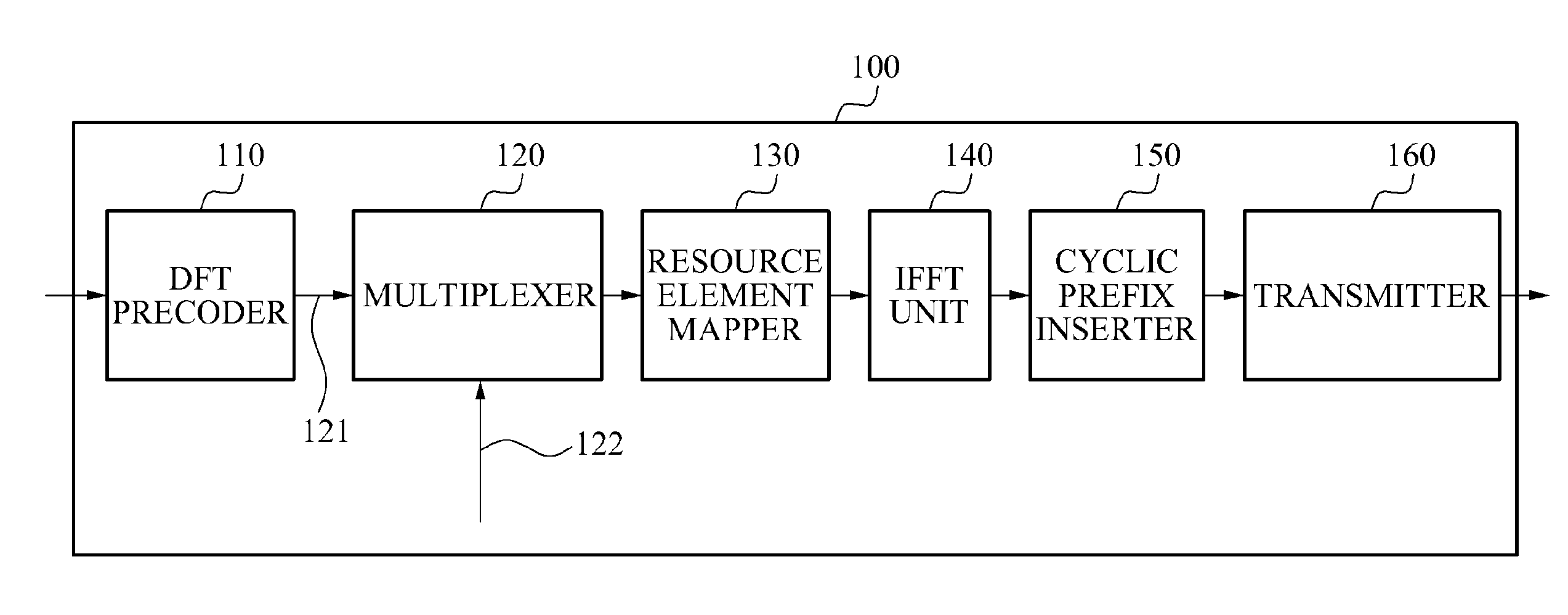
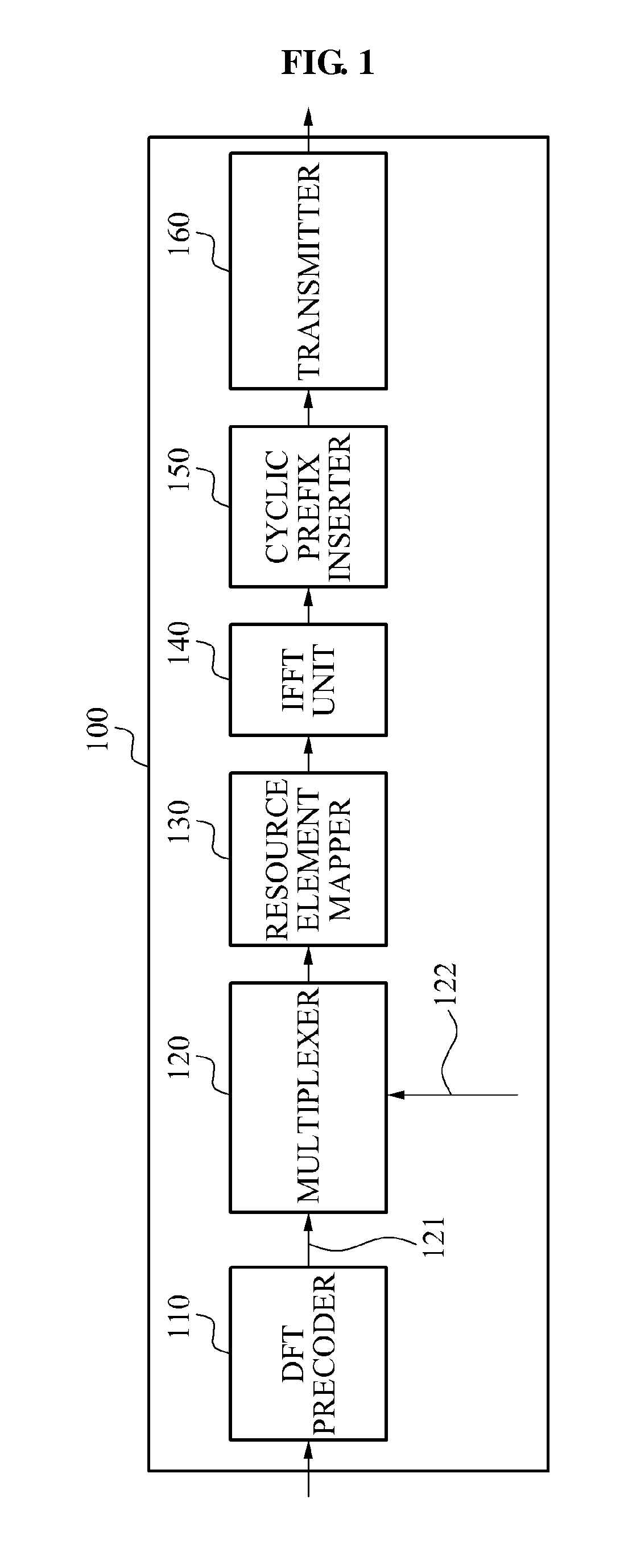
[0022]FIG. 1 is a diagram illustrating a structure of a data transmission apparatus according to an aspect of the present invention. The data transmission apparatus 100 includes a discrete Fourier transform (DFT) precoder 110, a multiplexer 120, a resource element mapper 130, an inverse fast Fourier transform (IFFT) unit 140, a cyclic prefix inserter 150, and a transmitter 160.

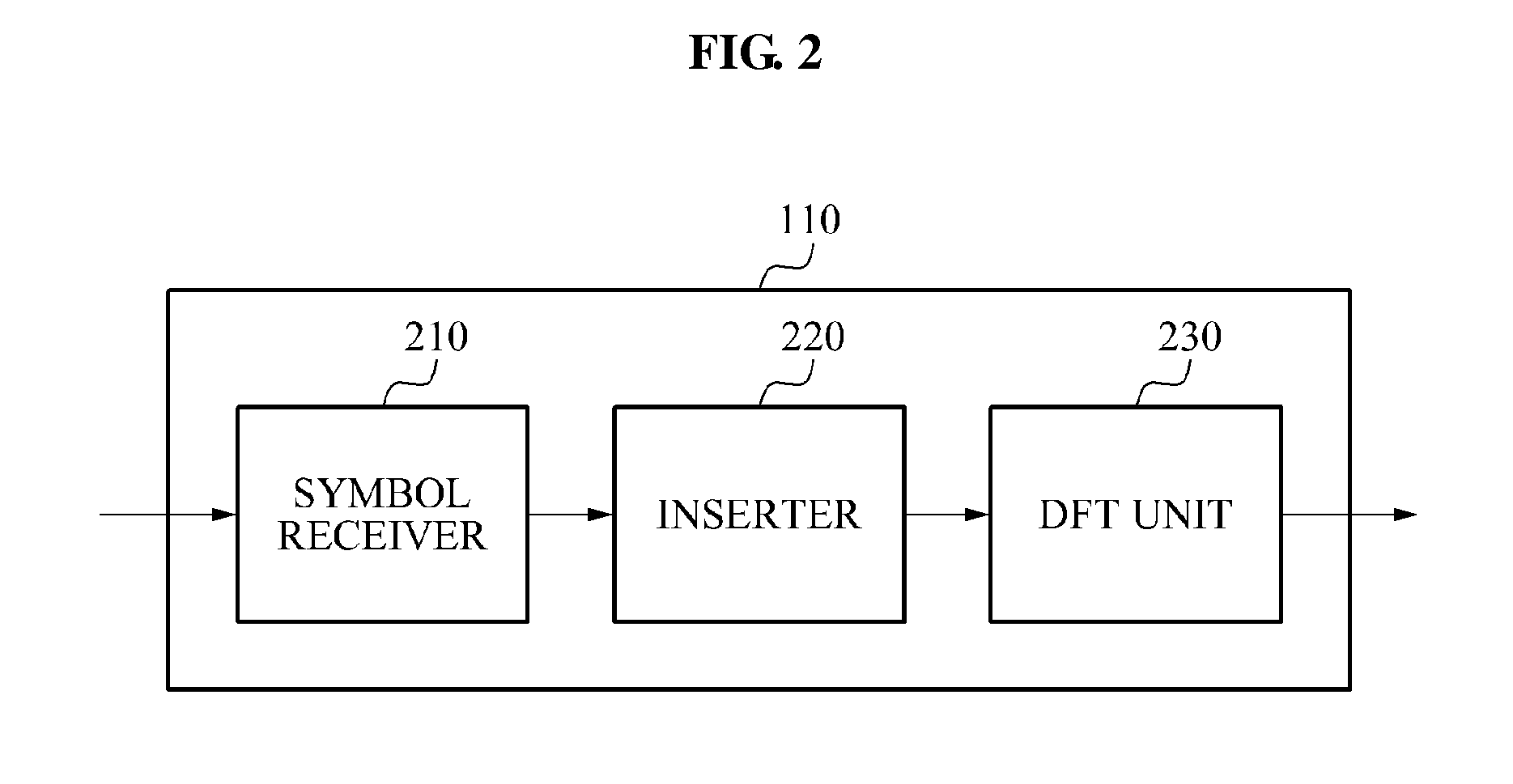
[0023]The DFT precoder 110 may perform a DFT with respect to a data symbol. According to an aspect, the data symbol that the DFT precoder 110 receives may be a complex data symbol caused to be channel coded, interleaved, scrambled, and modulated by a modulation technique such as binary phase...


PUM


Abstract

Provided is a data transmission apparatus to transmit a reference orthogonal frequency division multiplexing (OFDM) symbol generated by frequency division multiplexing a reference symbol and a data symbol, and a data reception apparatus to estimate a channel using the reference OFDM symbol. Since the reference symbol and the data symbol are frequency division multiplexed, a Peak to Average Power Ratio (PAPR) may not increase greatly, and the transmission apparatus may transmit the reference OFDM symbol to the data reception apparatus more frequently. Accordingly, the data reception apparatus may estimate a channel accurately.

Description

TECHNICAL FIELD[0001]The present invention relates to mobile communications, and more particularly, to a technique of transmitting a reference symbol for a channel estimation in an orthogonal frequency division multiplex (OFDM) communication system.BACKGROUND ART[0002]Digital Fourier transform spread orthogonal frequency division multiplexing to (DFT spread OFDM) method has a low Cubic Metric (CM) and equivalently low Peak to Average Power Ratio (PAPR). Therefore, a power amplifier may be used efficiently. With the merit, DFT spread OFDM method has been adopted as an uplink transmission method of 3rd Generation Partnership Project (3GPP) long term evolution (LTE) system, and it is considered that it will be adopted as an uplink transmission method of 3GPP LTE-Advanced. DFT spread OFDM is also referred to Single Carrier Frequency Division Multiple Access (SC-FDMA) equivalently.[0003]A reference symbol or a pilot signal is transmitted from a data transmission apparatus to a data recep...

Claims


Application Information

Patent Timeline
Patent Type & Authority Applications(United States)
IPC IPC(8): H04B1/69
CPCH04L5/0051H04L27/2636H04L27/2614H04L25/0224H04L27/2607H04L27/2613
Inventor JEONG, BYUNG JANGSEO, BANGWONAHN, JAE YOUNG
Owner ELECTRONICS & TELECOMM RES INST
Learn More