
Medical valve assembly

Active Publication Date: 2012-04-12
CODAN MEDIZINISCHE GERATE
View PDF2 Cites 9 Cited by
  • Summary
  • Abstract
  • Description
  • Claims
  • Application Information

AI Technical Summary

Benefits of technology

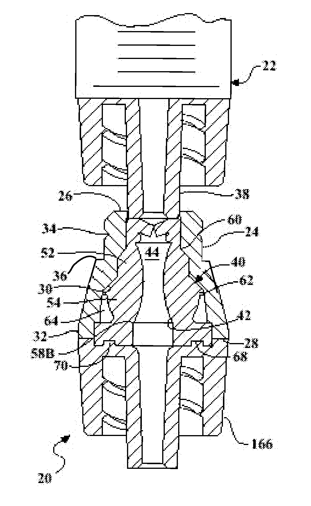
[0008]According to one aspect of the invention, the medical valve assembly includes a housing, a receiver, and a valve stem. The valve stem presents a passageway for the flow of fluid and is of a resilient material, such as silicone, for resiliently deforming when the luer of a needleless syringe is inserted into the valve stem through the stem slit. The passageway of the valve stem has an hourglass shape for bulging inwardly in response to compression of the valve stem. Because of the hourglass shape, the volume of the passageway is decreased as compared to a valve stem having straight inner walls which could lead to a reduced risk of infection from fluids remaining in the passageway when the medical valve assembly is not in use. This reduction of the inner diameter of the fluid pathway creates a venturi effect when fluid is infused rapidly, such as during flushing of the valve. This venturi effect results in a more effective and efficient cleaning of the interior surfaces of the fluid pathway, thereby ensuring that blood is completely removed. This efficient design permits a minimal amount of saline flush to achieve the desired result without the use of heparin, which is contraindicated in neonates and immune surpressed patients. In other words, the medical valve assembly is more safe and sanitary than the medical valve assemblies of the prior art.
[0009]According to another aspect of the invention, the valve stem defines a point of reduced wall thickness, or a point of weakness, for deforming and collapsing a portion of the valve stem inwardly and downwardly into the housing at the point of weakness. The volume of the passageway of the valve stem remains relatively constant when this portion of the valve stem buckles and subsequently returns to its resting space after the luer of the needleless syringe is removed. This has the effect of reducing aspiration of the fluid when the luer of the needleless syringe is removed from the valve stem.
[0010]The medical valve assembly permits infusion of fluids as well as aspiration of blood samples. In addition, the medical valve is designed to prevent the inadvertent aspiration of air into the patient by stopping the fluid meniscus before it reaches the needleless syringe. Thus, the mechanism improves patient safety and reduces staff stress, thus permitting the staff to attend to more urgent matters.

Problems solved by technology

This buckling movement of the valve stem changes the volume of the passageway and requires wasted space to allow for the valve stem to buckle outwardly.
However this open pathway can also lead to the serious patient complications, if left unattended.
The resulting air embolism can cause significant patient morbidity or death.
This can be prevented by placing a one way valve, or a check valve, between the needle free adapter and the IV tubing; however, this solution may be costly, a suitable check valve may not be available, and the additional connections and disconnections can be a source of contamination.

Method used


Image

  • Medical valve assembly
  • Medical valve assembly
  • Medical valve assembly

Examples


Embodiment Construction

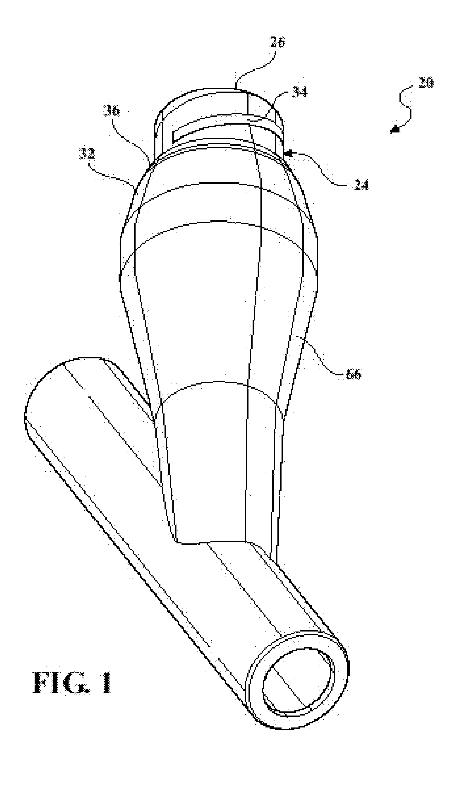
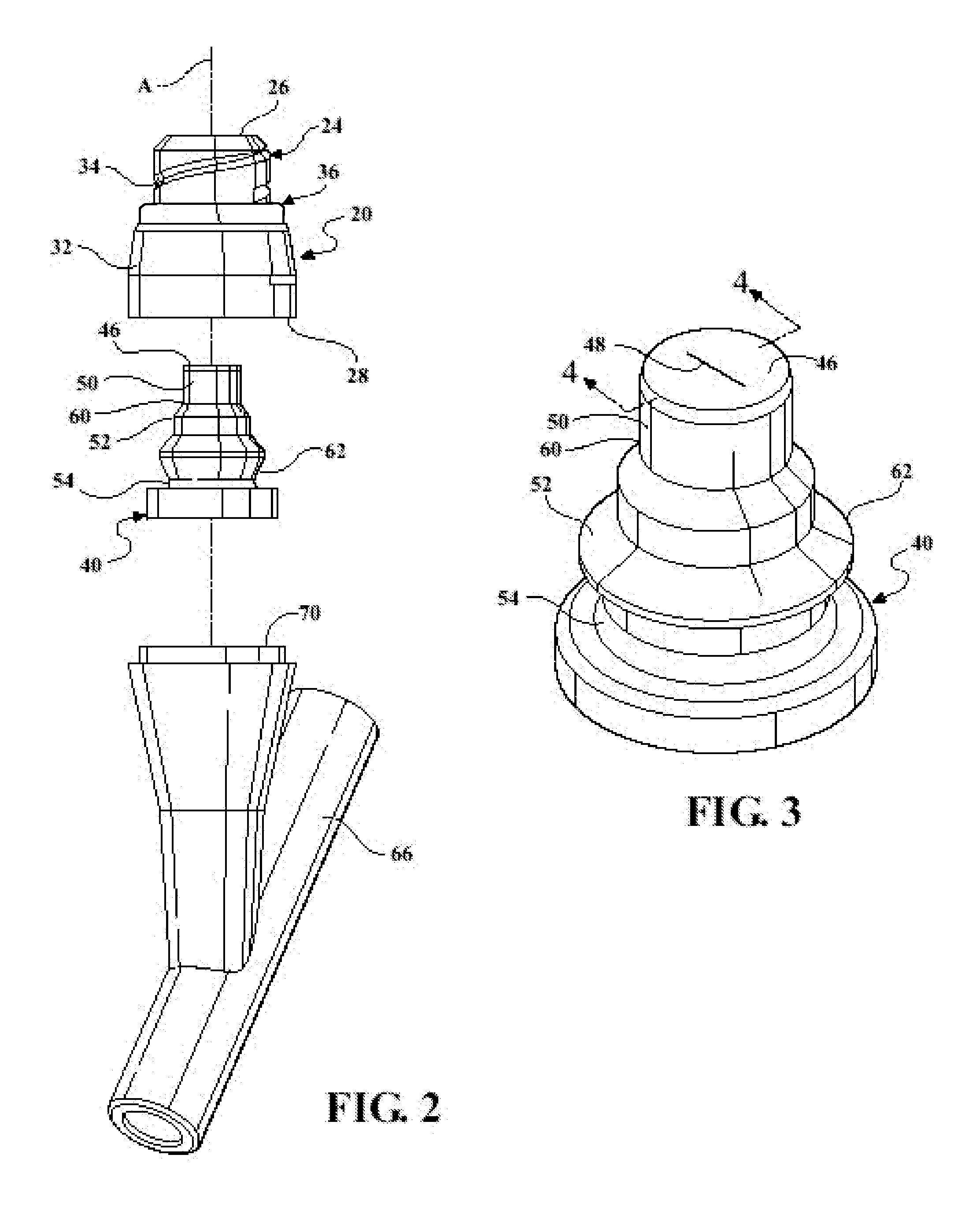
[0031]Referring to the Figures, wherein like numerals indicate corresponding parts throughout the several views, a first exemplary embodiment of a medical valve assembly 20 for receiving a fluid from a needleless device is generally shown in FIG. 1. The needleless device is hereinafter referred to as a needleless syringe 22, though it should be appreciated that the needleless device could be any desirable device for injecting and / or ejecting a fluid.

[0032]The first exemplary medical valve assembly 20 includes a rigid external housing 24, generally indicated, extending along an axis A from an open first housing end 26 to an open second housing end 28. Preferably, the housing 24 is made of a polymeric material, but it should be appreciated that the housing 24 can be made of any rigid material. The housing 24 defines a housing inner wall 30 and a housing exterior wall 32, which defines threads 34 adjacent to the first housing end 26 for threadedly engaging the needleless syringe 22. Th...


PUM


Abstract

A medical valve assembly including a rigid external housing and a valve stem of a resilient material. The valve stem includes a passageway for conveying a fluid which has an hourglass shape to create a venturi effect when cleaning the valve stem to improve the efficiency of the cleaning process. The passageway also includes no sharp edges, thus reducing the risk of fluid getting trapped inside the passageway when the medical valve assembly is not in use. Even further, when a needleless syringe is removed from the valve stem, the valve stem expands to an uncompressed state with its top end being generally flush with an end of the housing to present a swabable surface for cleaning purposes.

Description

CROSS REFERENCE TO RELATED APPLICATION[0001]This application claims the benefit of provisional application Ser. No. 61 / 392,063 filed Oct. 12, 2010 and of provisional Ser. No. 61 / 474,925, filed Apr. 13, 2011.BACKGROUND OF THE INVENTION[0002]1. Field of the Invention[0003]The invention relates to a medical valve assembly for receiving a fluid from a needleless syringe.[0004]2. Description of the Prior Art[0005]Needleless syringes are used in the medical field to deliver fluids to a patient without the risk of an accidental needle poke on either the patient or the person treating the patient. Needleless syringes generally include a luer for delivering the fluid to a medical valve and threads for threadedly engaging the medical valve. Various medical valves have been developed to engage the needleless syringes and deliver the fluid to an IV line of a patient. One such medical valve is shown in U.S. Pat. No. 6,651,956, issued to Pavel T. Miller on Nov. 25, 2003 (hereinafter referred to a...

Claims


Application Information

Patent Timeline
IPC IPC(8): A61M5/307A61M5/30
CPCA61M39/26A61M39/045A61M2039/261
Inventor HOKANSON, CHARLES
Owner CODAN MEDIZINISCHE GERATE
Learn More