

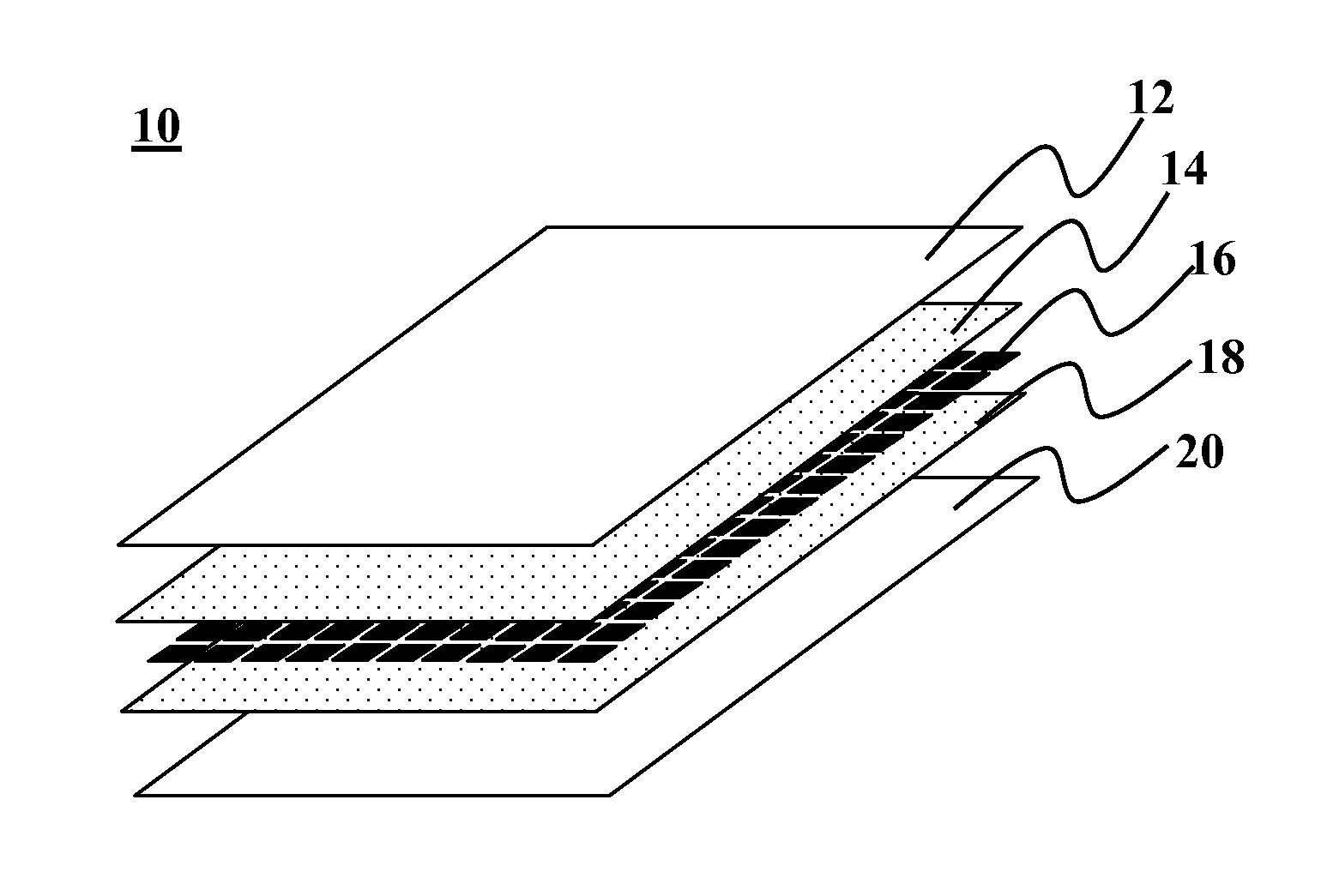
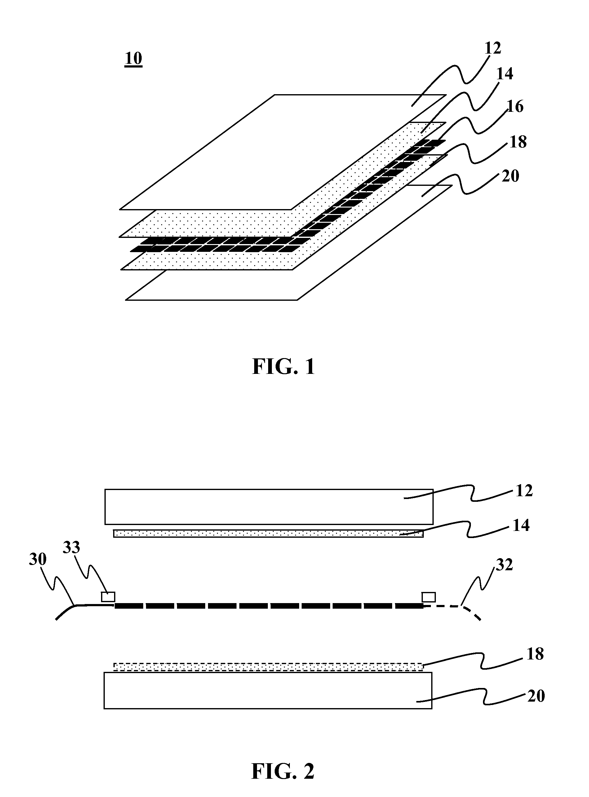
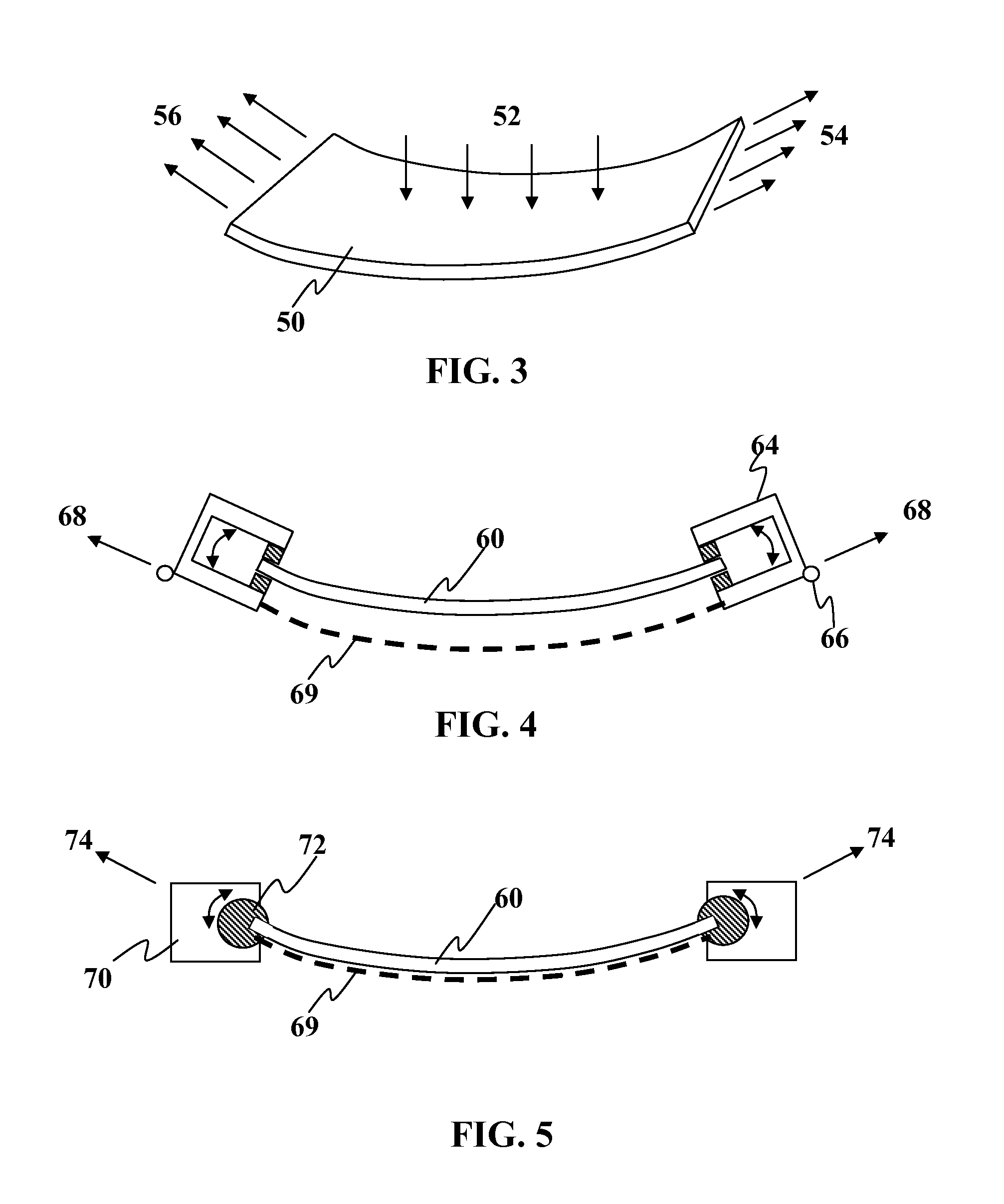
Tensioned mounting of solar panels
a solar panel and mounting bracket technology, applied in the field of photovoltaic devices, can solve the problems of limited the ability to install large numbers of solar panels in a cost-effective manner, limited the ability to create larger solar panels and/or solar panels using less expensive materials, and limited the ability to make such panels. the effect of reducing manufacturing costs and redundant parts
- Summary
- Abstract
- Description
- Claims
- Application Information
AI Technical Summary
Benefits of technology
Problems solved by technology
Method used
Image

Examples
Embodiment Construction
[0055]It is to be understood that both the foregoing general description and the following detailed description are exemplary and explanatory only and are not restrictive of the invention, as claimed. It may be noted that, as used in the specification and the appended claims, the singular forms “a”, “an” and “the” include plural referents unless the context clearly dictates otherwise. Thus, for example, reference to “a material” may include mixtures of materials, reference to “a compound” may include multiple compounds, and the like. References cited herein are hereby incorporated by reference in their entirety, except to the extent that they conflict with teachings explicitly set forth in this specification.
[0056]In this specification and in the claims which follow, reference will be made to a number of terms which shall be defined to have the following meanings:
[0057]“Optional” or “optionally” means that the subsequently described circumstance may or may not occur, so that the des...
PUM
| Property | Measurement | Unit |
|---|---|---|
| total photovoltaic surface area | aaaaa | aaaaa |
| total photovoltaic surface area | aaaaa | aaaaa |
| total photovoltaic surface area | aaaaa | aaaaa |
Abstract
Description
Claims
Application Information