Water heater and control method therefor

a technology for water heaters and control methods, applied in the field of water heaters, can solve the problems of excessive heat exchange of fin pipes of heat exchangers, insufficient heat exchange between exhaust and supplied water, and damage to heat exchangers

Active Publication Date: 2012-04-19
PURPOSE CO LTD
View PDF5 Cites 75 Cited by
  • Summary
  • Abstract
  • Description
  • Claims
  • Application Information

AI Technical Summary

Benefits of technology

[0027](2) Opening and closing operation of flow rate adjustment mea...

Problems solved by technology

Further, there is also a case where air stays in pipes when the water heater has not been used for a long time.
When remaining air stays inside a heat exchanger, heat is not exchanged sufficiently between exhaust and supplied water.
Especially, when the flow rate of the supplied water to the inside of the heat exchanger is low, heating the water to setting temperature is difficult because air remaining thereinside cannot be pushed out.
There is a problem that when remaining air stays inside a heat exchanger and heat is not exchanged sufficiently continuously, there...

Method used


Image

  • Water heater and control method therefor
  • Water heater and control method therefor
  • Water heater and control method therefor

Examples


first embodiment

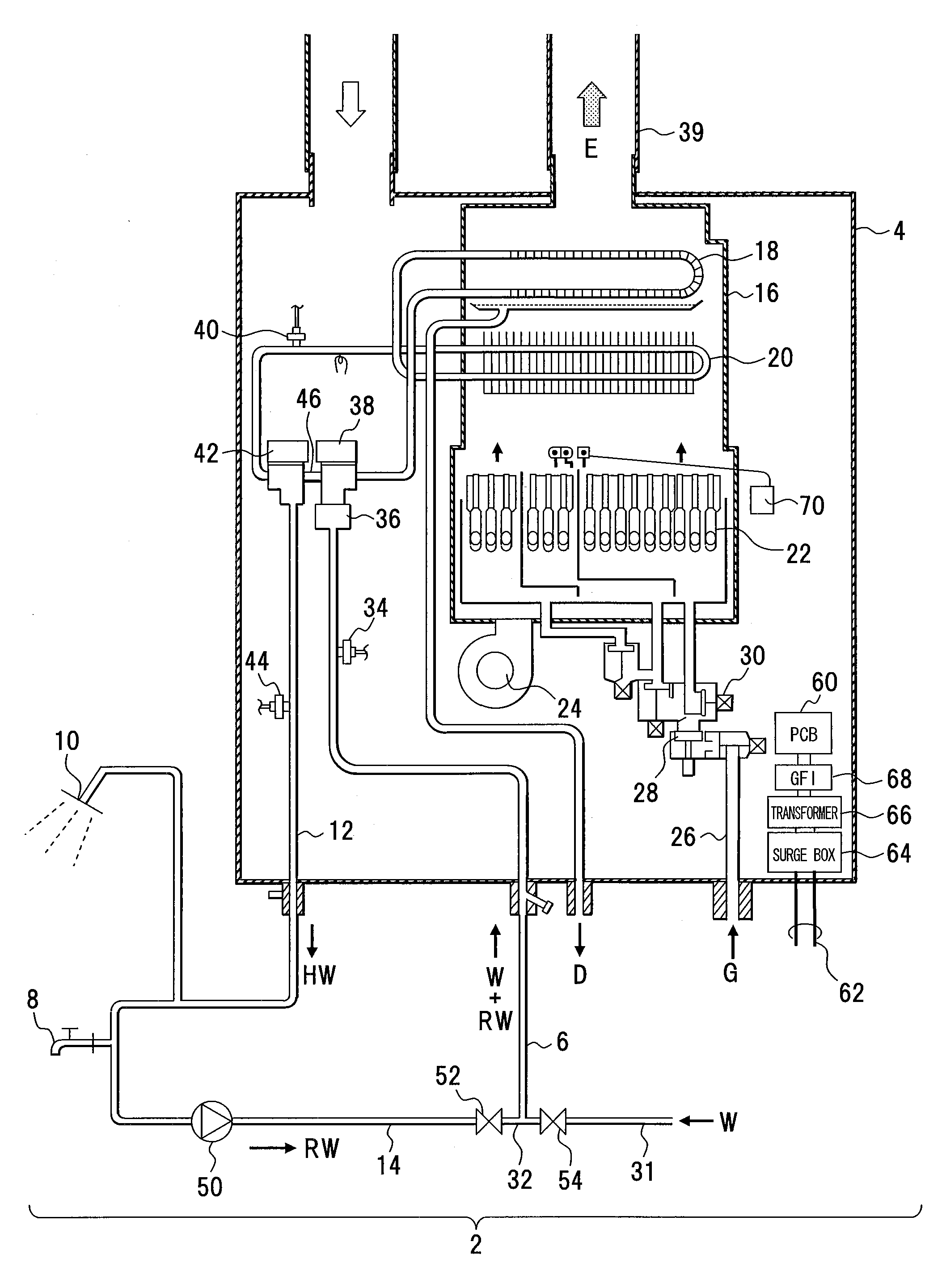
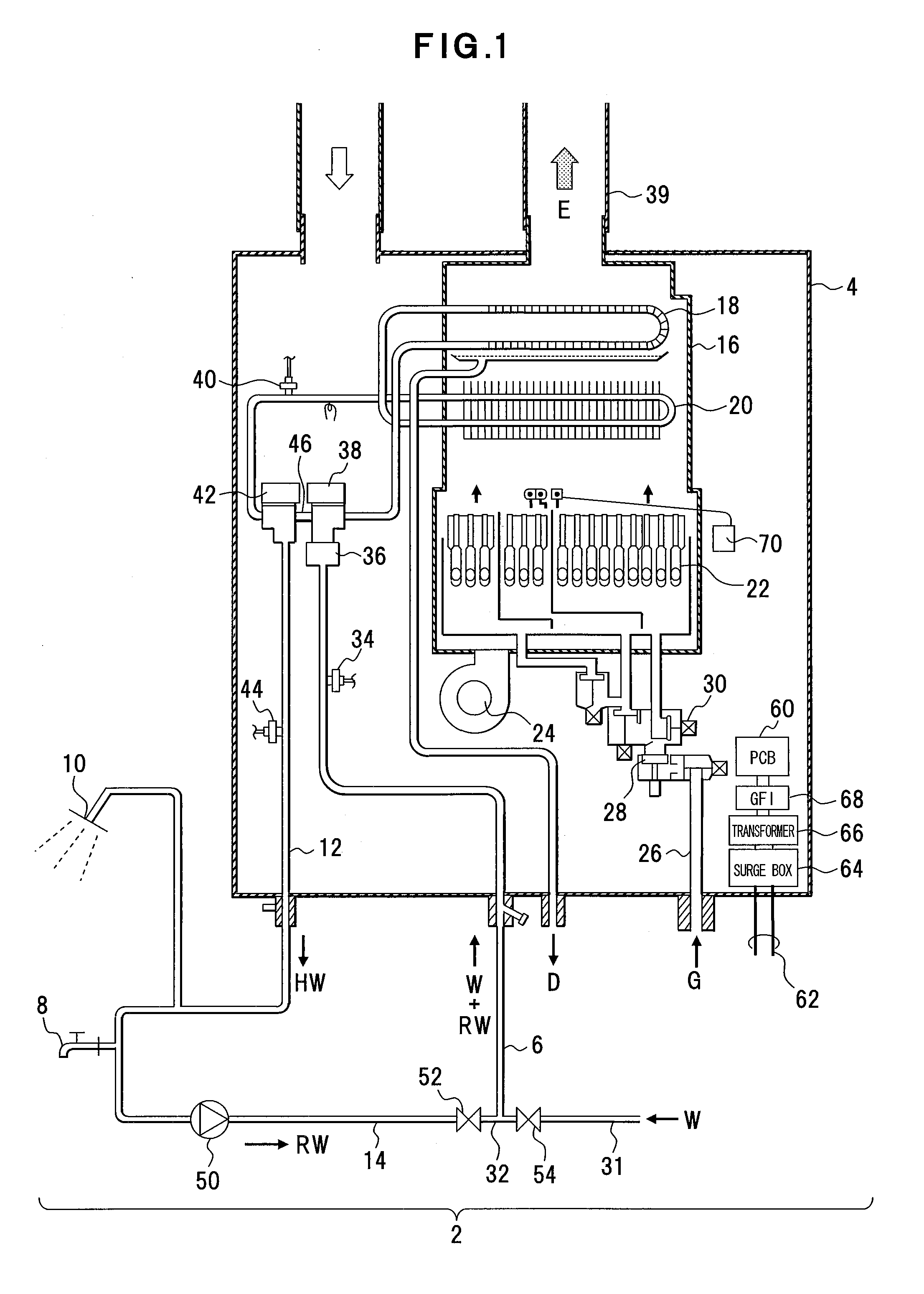
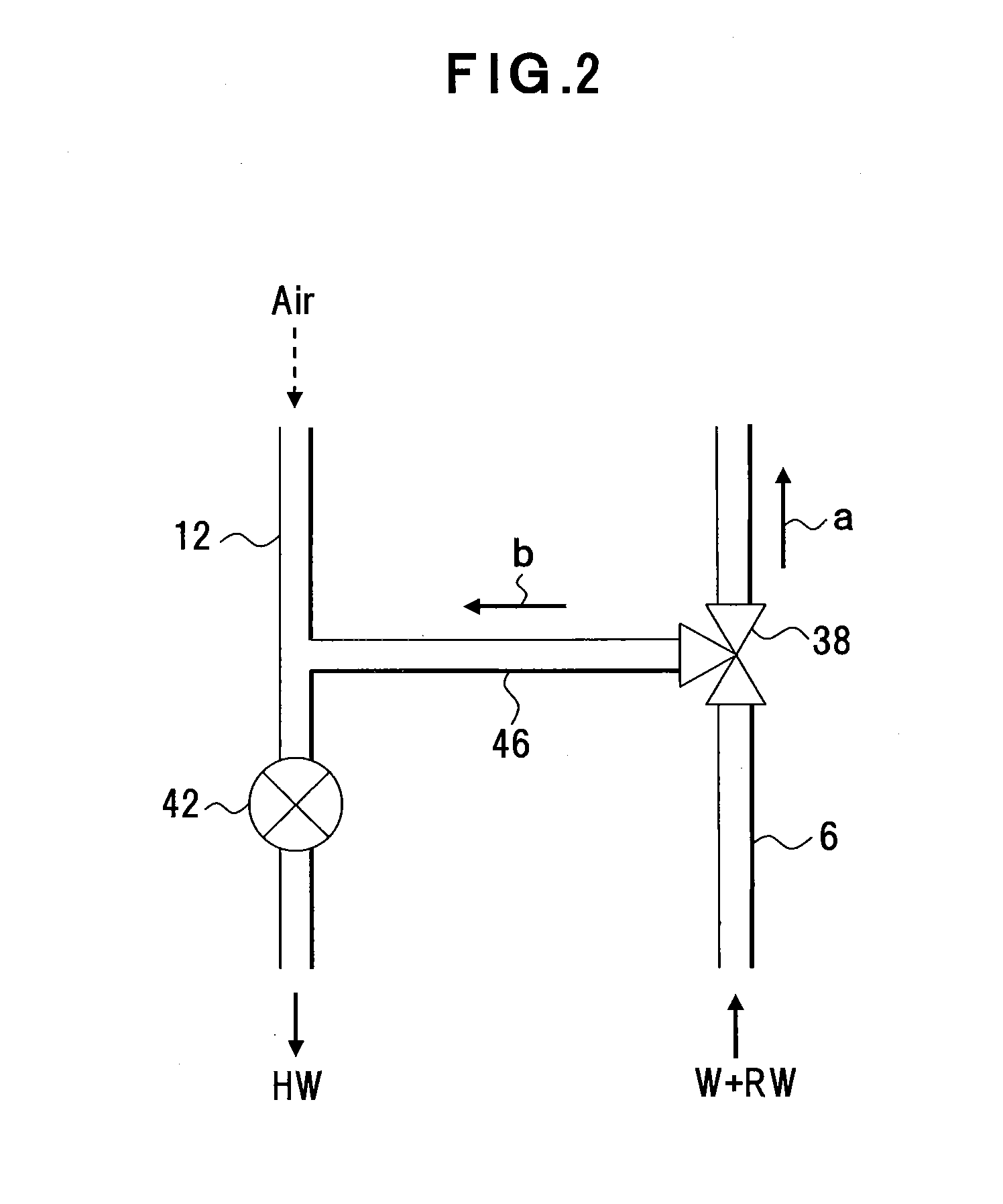
[0040]A first embodiment will be described with reference to FIGS. 1 and 2. FIG. 1 depicts an example of structure of a water heater according to the first embodiment and FIG. 2 depicts an example of structure of a bypass valve and an example of flow rate adjustment by the bypass valve. Each structure depicted in FIGS. 1 and 2 is an example, and thus the present invention is not limited to such structure.

[0041]This water heater 2 is an example of a water heater of the present disclosure, and includes a combustion device 4 that heats supplied water such as tap water W to supply hot water, a water supply pipe 6 that supplies water to the combustion device 4 and a hot water supply pipe 12 that supplies hot water HW from the combustion device 4 to a hot water outlet 8 or a shower 10. The hot water supply pipe 12 has a circulation line 14 that makes the hot water HW, flowing through the hot water outlet 8 etc., join the water supply pipe 6 as return water RW and circulates the hot water ...

second embodiment

[0097]A second embodiment will be described with reference to FIGS. 7 and 8. FIGS. 7 and 8 are flowchart depicting an example of a remaining air prevention control process during combustion according to the second embodiment. Each processing content and processing procedure depicted in FIGS. 7 and 8 is an example, and the present invention is not limited thereto. A, B and C in the figures depict connectors.

[0098]Here, an example of another control process will be depicted for lowering setting temperature for heat exchange during combustion operation of the combustion device 4 and securing the flow rate of supplied water for the heat exchangers 18 and 20.

[0099]It is determined whether to be the setting temperature Ts that allows the operation of the bypass valve 38 (step S31). This setting temperature Ts is an example of a setting value of outgoing hot water temperature required for the water heater 2. The opening or closing operation of the bypass valve 38 is permitted when the sett...

third embodiment

[0110]A third embodiment will be described with reference to FIG. 9. FIG. 9 depicts an example of structure of a water heater according to a third embodiment. Structure depicted in FIG. 9 is an example, and thus the present invention is not limited to such structure. In FIG. 9, the same components as those in FIG. 1 etc. are denoted by the same reference numerals, and description thereof is omitted.

[0111]This water heater 150 is an example of a water heater of the present invention. In the water heater 150, for example, some of plural combustion devices 4A to 4D, which are equivalent, are disposed in parallel, and the hot water HW is supplied to a hot water supply part using the water supply pipe 6 and the hot water supply pipe 12 commonly. In the water heater 150, the combustion devices 4A to 4D, the water supply pipe 6 and the hot water supply pipe 12 are circulated through the circulation line 14 disposed in the hot water supply part, and heat of hot water circulated therethrough...


PUM


Abstract

A water heater includes combustion means (burner) that combusts fuel and generates exhaust; heat exchange means (primary heat exchanger and secondary heat exchanger) that exchanges heat of the exhaust for supplied water; bypassing means (bypass pipe) that makes the supplied water flow to an outlet of the heat exchange means; exchanged heat temperature detection means (exchanged heat temperature sensor) that detects temperature of the supplied water after heat exchange; flow rate adjustment means (bypass valve) that adjusts a volume of the supplied water flowing into the bypassing means and the heat exchange means; and a control unit that controls the flow rate adjustment means so as to make a predetermined volume of the supplied water or over flow to the heat exchange means.

Description

BACKGROUND OF THE INVENTION[0001]1. Field of the Invention[0002]The present invention relates to a water heater in which the supply of hot water and temperature thereof are adjusted to a required level, and in which air staying in pipes, especially in a heat exchanger is discharged.[0003]2. Description of the Related Art[0004]There is a case where remaining air stays inside a water supply pipes etc. in a water heater. This remaining air may stay while concentrating in a certain place according to the arrangement of pipes in the water heater. There is also a case where warmer air stays in upper pipes in the water heater compared with cooler water according to a change in temperature of water or hot water in the pipes. Further, there is also a case where air stays in pipes when the water heater has not been used for a long time.[0005]When remaining air stays inside a heat exchanger, heat is not exchanged sufficiently between exhaust and supplied water. Especially, when the flow rate o...

Claims


Application Information

Patent Timeline
IPC IPC(8): F24H9/20
CPCF24H1/145F24H8/00F24H8/006F24H9/128F24H9/2028F24H9/2035Y02B30/106F24D17/0078F24D19/1051G05D23/1917F24D2200/043F24D2220/044Y02B30/102F24D17/0026Y02B30/00F24H9/139F24H15/335F24H15/31F24H15/486F24H15/45F24H15/269F24H15/395F24H15/345F24H15/219F24H15/215F24H15/325F24H15/36F24H15/25F24H15/421F24H15/238F24H15/281F24H15/175
Inventor IWAMA, KAZUSHIWATANABE, AKITOAISO, JUN
Owner PURPOSE CO LTD
Why Eureka
Try Eureka