Electrodynamic braking device for a universal motor

a technology of electrodynamic braking and universal motor, which is applied in the direction of motor/generator/converter stopper, dynamo-electric converter control, ac motor stopper, etc., can solve the problems that the electrodynamic braking devices known are not sufficiently suitable for the intended application, and achieve good braking, good braking effect, and reduced brush sparking

Active Publication Date: 2012-04-19
ROBERT BOSCH GMBH
View PDF10 Cites 10 Cited by
  • Summary
  • Abstract
  • Description
  • Claims
  • Application Information

AI Technical Summary

Benefits of technology

[0012]Therefore, the invention is based on the object of providing an effective and cost-effective electrodynamic braking device for a universal motor, which results in good braking with reduced brush sparking and little brush wear and which, by means of an appropriate circuit arrangement, ensures operationally reliable monitored braking operation and motor operation, in order to allow a braking device such as this to be used for a machine which is fitted with a dangerous tool.

Problems solved by technology

The known electrodynamic braking devices are not sufficiently suitable for the intended application.

Method used


Image

  • Electrodynamic braking device for a universal motor
  • Electrodynamic braking device for a universal motor
  • Electrodynamic braking device for a universal motor

Examples


Embodiment Construction

[0019]Electrical handheld tools which are fitted with a dangerous tool, such as handheld circular saws and angle grinders, have until now been braked by a mechanical brake or by an electronic braking device.

[0020]In particular, a mechanical brake has the disadvantage that a brake such as this is subject to not inconsiderable wear and therefore requires maintenance, and previously known electronic braking devices have the considerable disadvantage that the brushes and the commutator in the normally used universal motors are subject to heavy wear during braking operation.

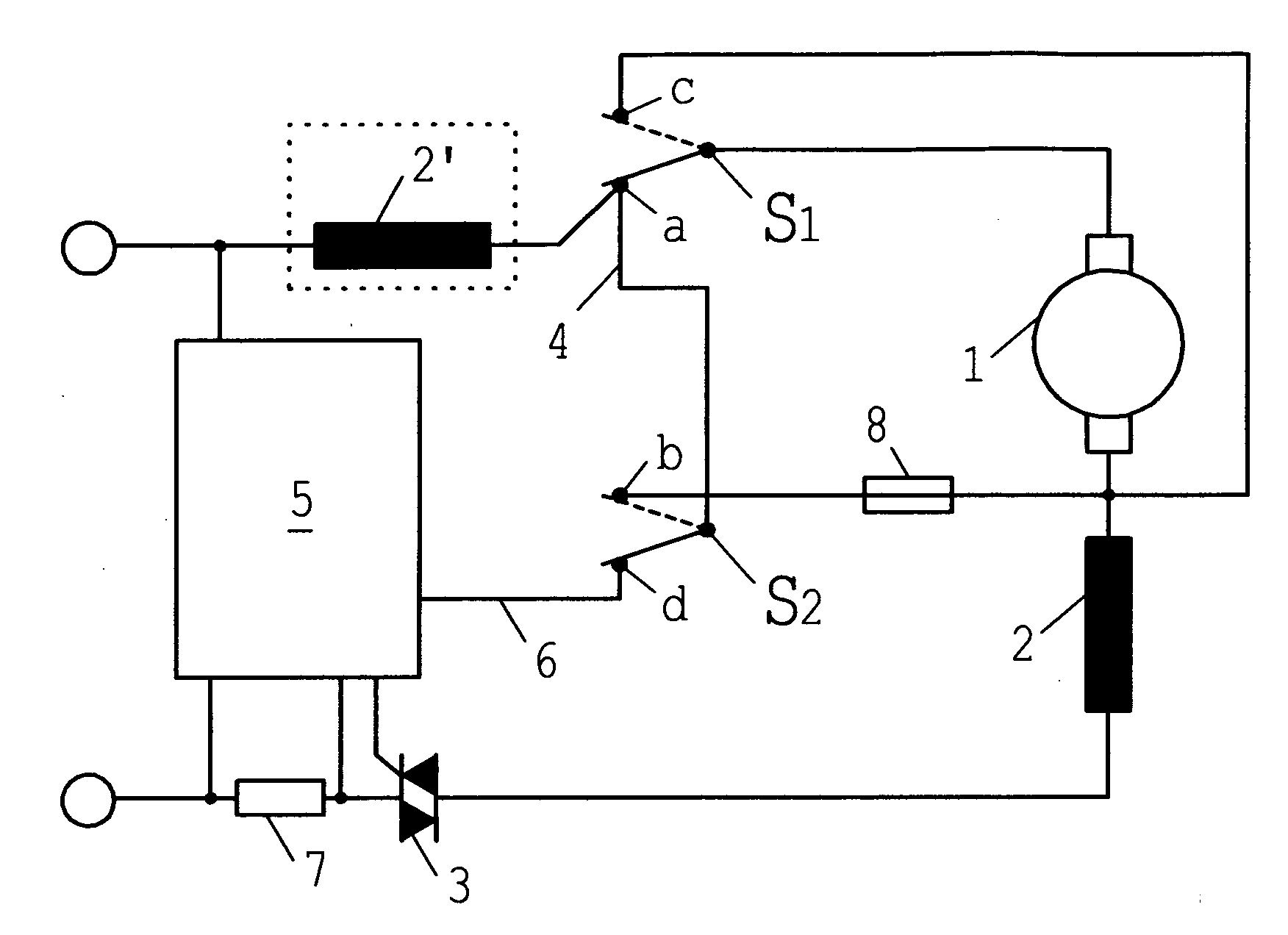
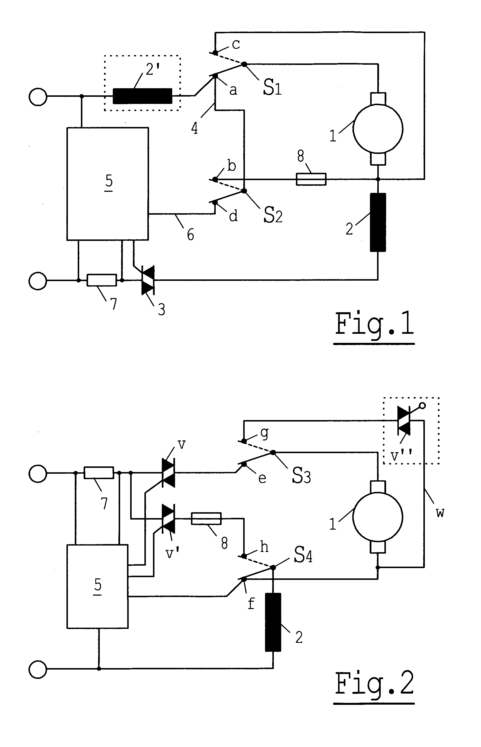
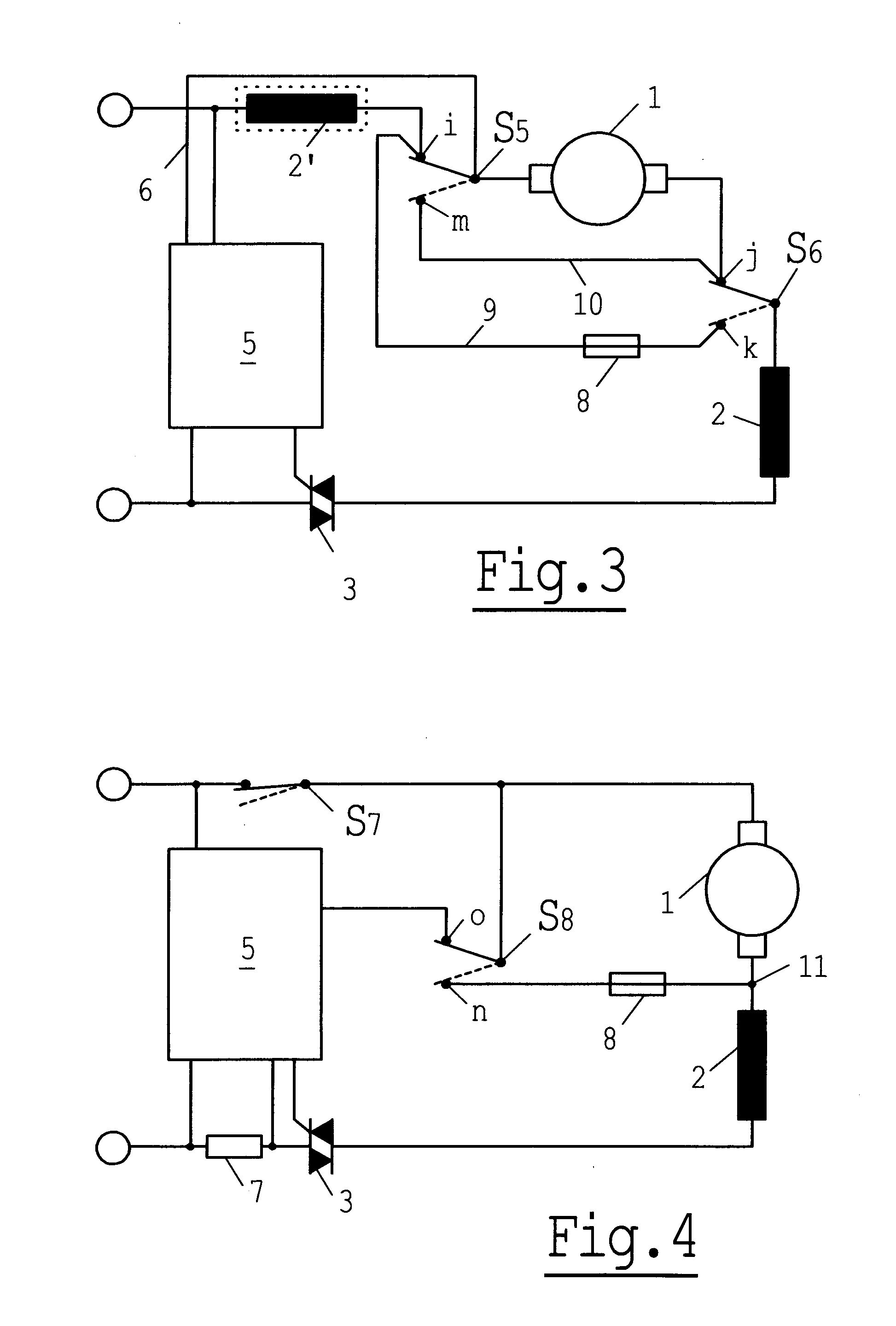
[0021]FIGS. 1 to 4 each show a circuit arrangement for a universal motor, by means of which shorting braking can be carried out depending on the power supply system, without the brushes being subjected to significant wear.

[0022]FIG. 1 shows a circuit arrangement in which a first power supply system connection leads to the motor operating contact a of a first switching element S1, and a first connection of an armature ...


PUM


Abstract

An electrodynamic braking device for a universal motor is proposed, wherein during a braking operation a field winding is supplied from a network, and an armature is directly short-circuited, and a braking operation is carried out using a program of a controller of a control electronics system, whereby good braking is achieved with relatively low brush wear. Such an electrodynamic braking device is advantageously applied in a power tool equipped with a dangerous tool.

Description

BACKGROUND OF THE INVENTION[0001]The invention relates to an electrodynamic braking device for a universal motor.[0002]Various embodiments of electrodynamic braking devices are known.[0003]DE 38 25 835 A1 describes an electrical braking apparatus for a series-wound motor, having a field winding and an armature and having a circuit arrangement with phase gating control, wherein, during braking operation, the field winding is fed from the power supply system and the armature is shorted.[0004]This braking apparatus is intended for a centrifuge, with the aim of keeping the braking torque constant over the entire rotation-speed range. The braking torque is controlled by a rotation-speed-dependent control device, with a current which is inversely proportional to the rotation speed of the electric motor being produced in the field winding of the electric motor. In addition, a braking resistor is also connected in series with the armature during braking operation.[0005]EP 0 721 694 B1 descr...

Claims


Application Information

Patent Timeline
Patent Type & Authority Applications(United States)
IPC IPC(8): H02P3/22
CPCH02M2005/2937H02P25/14H02P3/22H02M5/2937
Inventor ROTTMERHUSEN, HANS HERMANN
Owner ROBERT BOSCH GMBH
Why Eureka
Try Eureka