Eureka AIR delivers breakthrough ideas for toughest innovation challenges, trusted by R&D personnel around the world.

Thermal fly height control magnetic recording head having a novel heating element geometry

Active Publication Date: 2012-04-19
WESTERN DIGITAL TECH INC
View PDF10 Cites 5 Cited by
  • Summary
  • Abstract
  • Description
  • Claims
  • Application Information

AI Technical Summary

Benefits of technology

[0007]This configuration of the heating element has been found to provide optimal heater performance, providing optimal protrusion around the center of data track while minimizing heating / protrusion of adjacent track areas.

Problems solved by technology

One problem associated with such heating elements is the consistency of touch down detection.

Method used


Image

  • Thermal fly height control magnetic recording head having a novel heating element geometry
  • Thermal fly height control magnetic recording head having a novel heating element geometry
  • Thermal fly height control magnetic recording head having a novel heating element geometry

Examples


Embodiment Construction

[0015]The following description is of the best embodiments presently contemplated for carrying out this invention. This description is made for the purpose of illustrating the general principles of this invention and is not meant to limit the inventive concepts claimed herein.

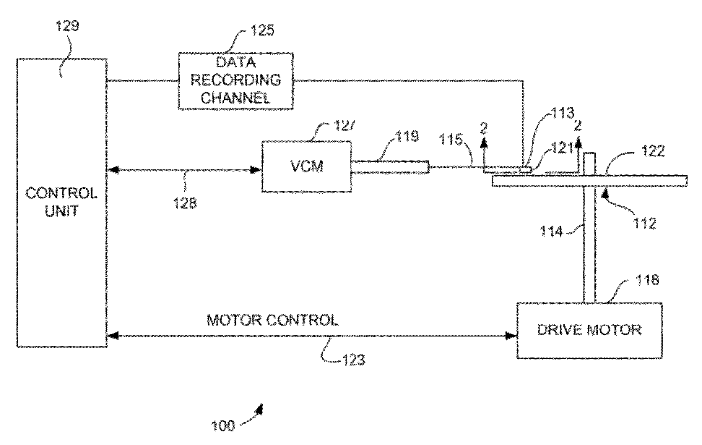
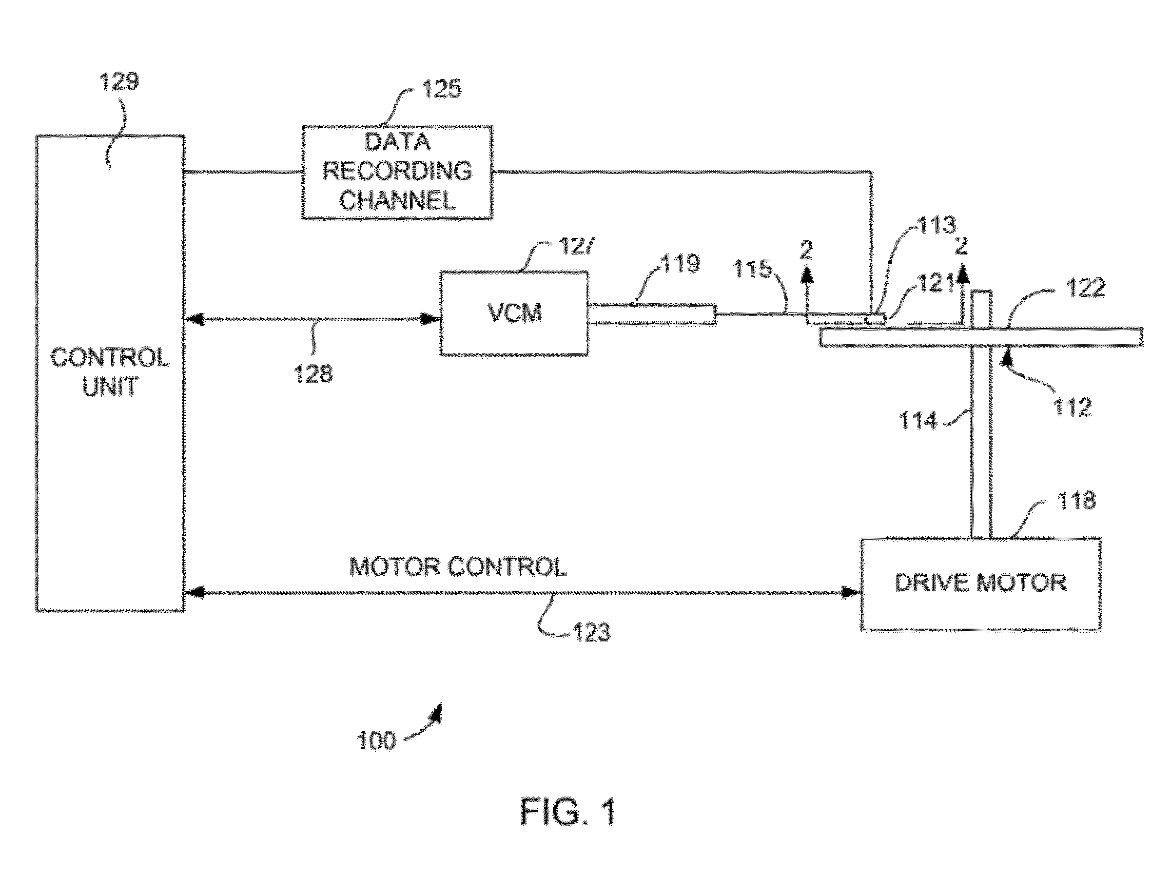
[0016]Referring now to FIG. 1, there is shown a disk drive 100 embodying this invention. As shown in FIG. 1, at least one rotatable magnetic disk 112 is supported on a spindle 114 and rotated by a disk drive motor 118. The magnetic recording on each disk is in the form of annular patterns of concentric data tracks (not shown) on the magnetic disk 112.

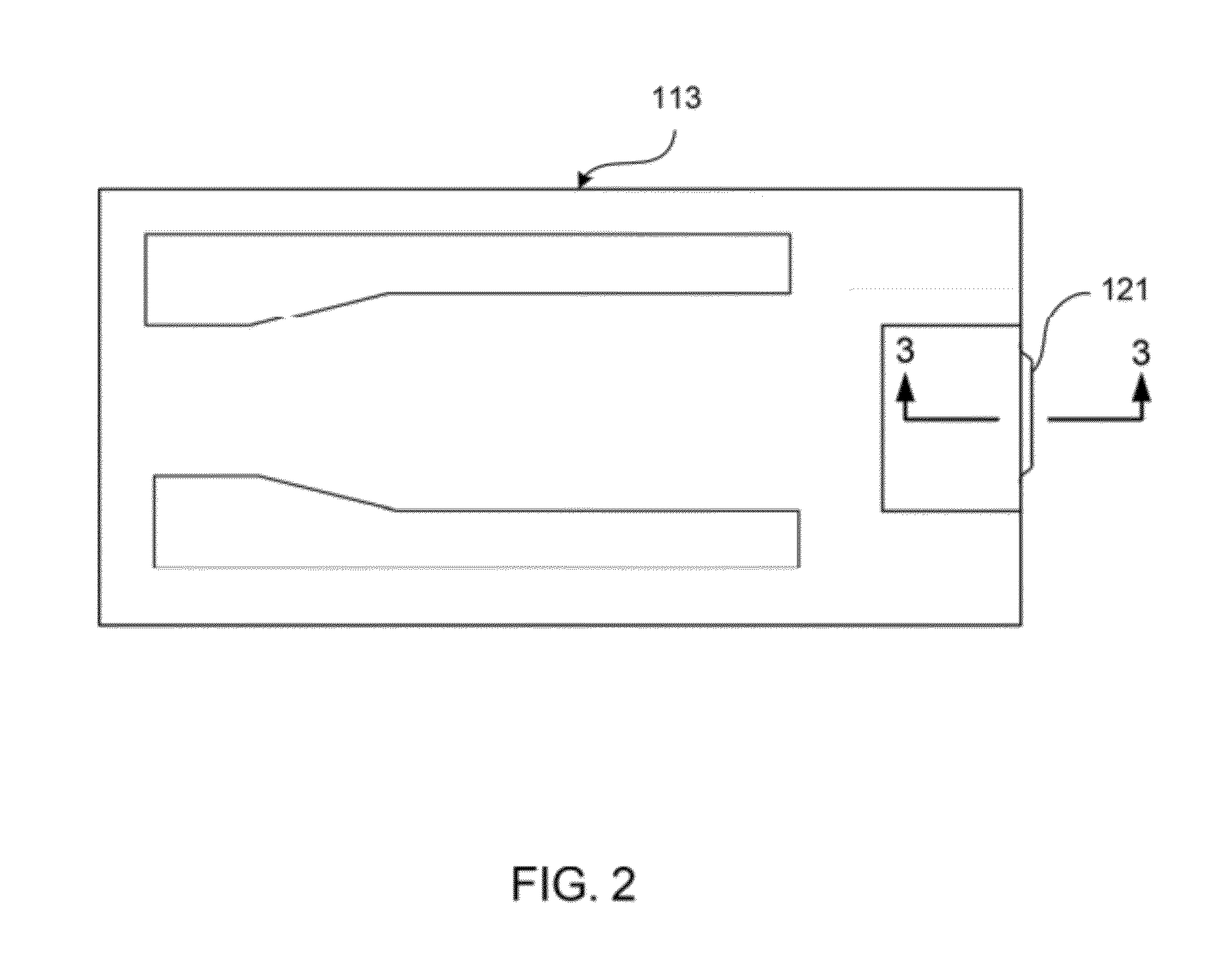
[0017]At least one slider 113 is positioned near the magnetic disk 112, each slider 113 supporting one or more magnetic head assemblies 121. As the magnetic disk rotates, slider 113 moves radially in and out over the disk surface 122 so that the magnetic head assembly 121 may access different tracks of the magnetic disk where desired data are written. Each slider 1...


PUM


Abstract

A heating element for use in a thermal fly height control magnetic recording head of a magnetic data recording system. The heating element has a centrally disposed portion with a straight front edge that is recessed by a substantially constant distance, and has first and second side portions that taper away from the air bearing surface. The side portions preferably taper away from the air bearing surface by an angle of 20 to 45 degrees. The center portion of the front edge is spaced from the air bearing surface by a distance D and has a width W, such that W is 1.5 to 2.5 (or about 2) times D. D is typically 2-6 um to have good heater efficiency while being large enough to not over heat the heater. The heating element has an overall width WW and a overall depth HH from the air bearing surface such that WW is 1.5-2.5 (or about 2) times HH.

Description

FIELD OF THE INVENTION[0001]The present invention relates to perpendicular magnetic write heads and more particularly to a thermal fly height control magnetic write head having a novel heater element design.BACKGROUND OF THE INVENTION[0002]The heart of a computer's long term memory is an assembly that is referred to as a magnetic disk drive. The magnetic disk drive includes a rotating magnetic disk, write and read heads that are suspended by a suspension arm adjacent to a surface of the rotating magnetic disk and an actuator that swings the suspension arm to place the read and write heads over selected circular tracks on the rotating disk. The read and write heads are directly located on a slider that has an air bearing surface (ABS). The suspension arm biases the slider toward the surface of the disk, and when the disk rotates, air adjacent to the disk moves along with the surface of the disk. The slider flies over the surface of the disk on a cushion of this moving air. When the s...

Claims


Application Information

Patent Timeline
IPC IPC(8): G11B5/02
CPCG11B5/607G11B5/3133
Inventor HSIAO, WEN-CHIEN D.SHEN, XINJIANGZHANG, JING
Owner WESTERN DIGITAL TECH INC
Why Eureka
Eureka Blog
Learn More