Light guide for illumination

a technology of light guide and light guide, which is applied in the field of light guide and luminaire, can solve the problems of unfavorable user experience and lack of appealing presentation, and achieve the effects of less light leakage, less light leakage, and efficient interfa

Inactive Publication Date: 2012-04-19
KONINKLIJKE PHILIPS ELECTRONICS NV
View PDF2 Cites 2 Cited by
  • Summary
  • Abstract
  • Description
  • Claims
  • Application Information

AI Technical Summary

Benefits of technology

[0017]At least one side may be a reflecting wall normal to the planar light emitting surface and extend along a symmetry axis of the equilateral triangle. The light guide may then still enjoy the advantages of the equilaterally triangular shaped light guide in addition to providing more freedom for selecting a shape of the light guide.
[0018]The light in-coupling corner may be defined by an in-coupling surface formed between adjacent slanting sides. Thereby, efficient in-coupling of light into the light guide may be achieved. By placing e.g. an LED adjacent the in-coupling surface, more light may be in-coupled into the light guide.
[0019]The light guide may have a planar top surface, wherein the planar top surface and the planar light emitting surface converge towards each other in at least one corner, wherein the surfaces converge until intersecting the in-coupling surface. Beneficially, more collimated in-coupling into the light guide may thereby be achievable. In particular, the four slanting surfaces converging towards the in-coupling surface at the corner each provide collimation parallel with the planar light emitting surface. By providing such collimation, fulfillment of present anti-glare norms for e.g. downlight applications may be achieved.
[0020]The at least one light in-coupling corner may have a rectangular shaped in-coupling surface. Thereby a light source such as an LED may more efficiently interface with the in-coupling surface providing less light leakage between the light guide and the light source.

Problems solved by technology

However, this solution does not suit particularly well for general illumination purposes, because it has a complicated design, it's bulky and lacks an appealing presentation to a user.

Method used


Image

  • Light guide for illumination
  • Light guide for illumination
  • Light guide for illumination

Examples


first embodiment

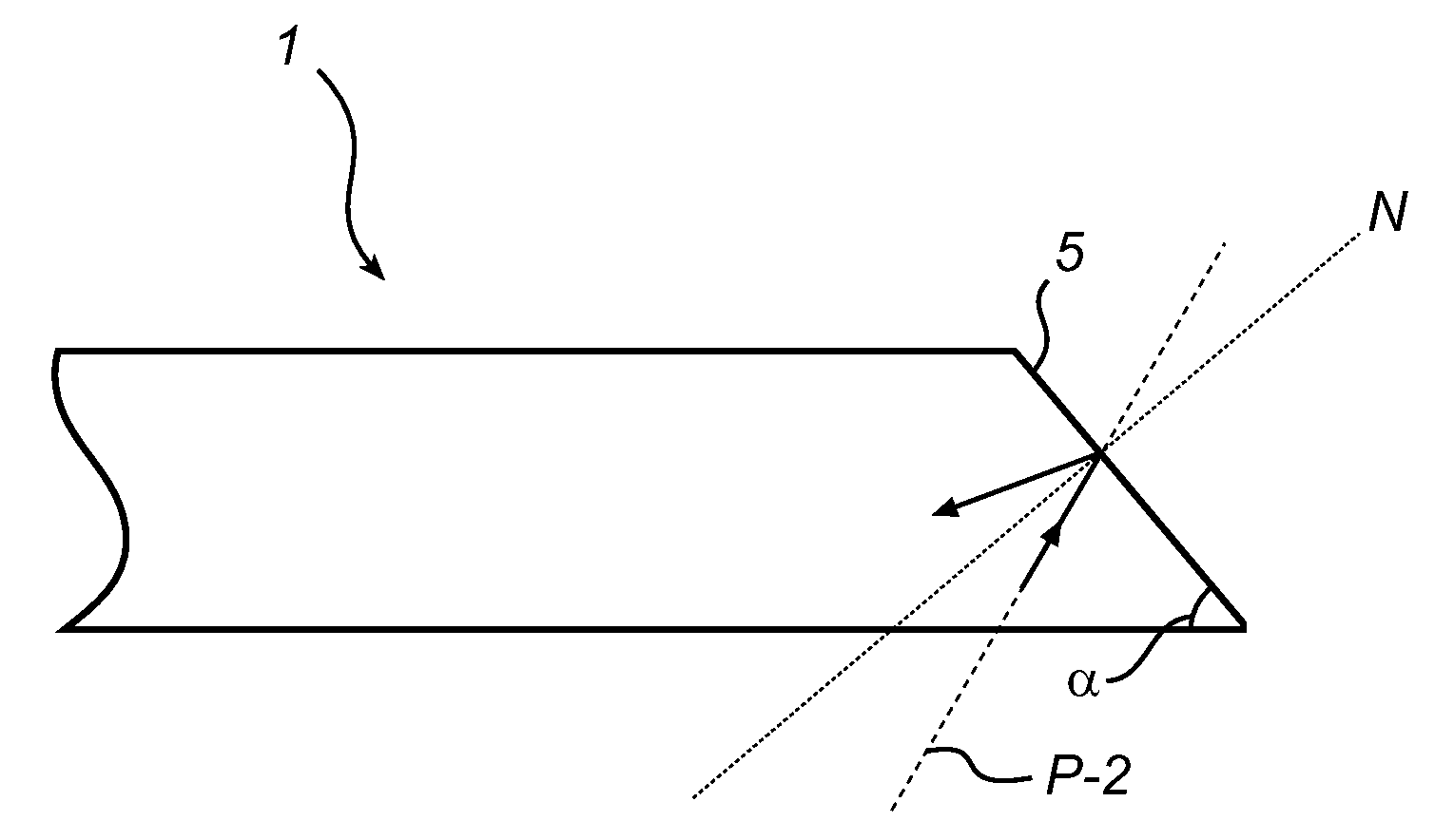
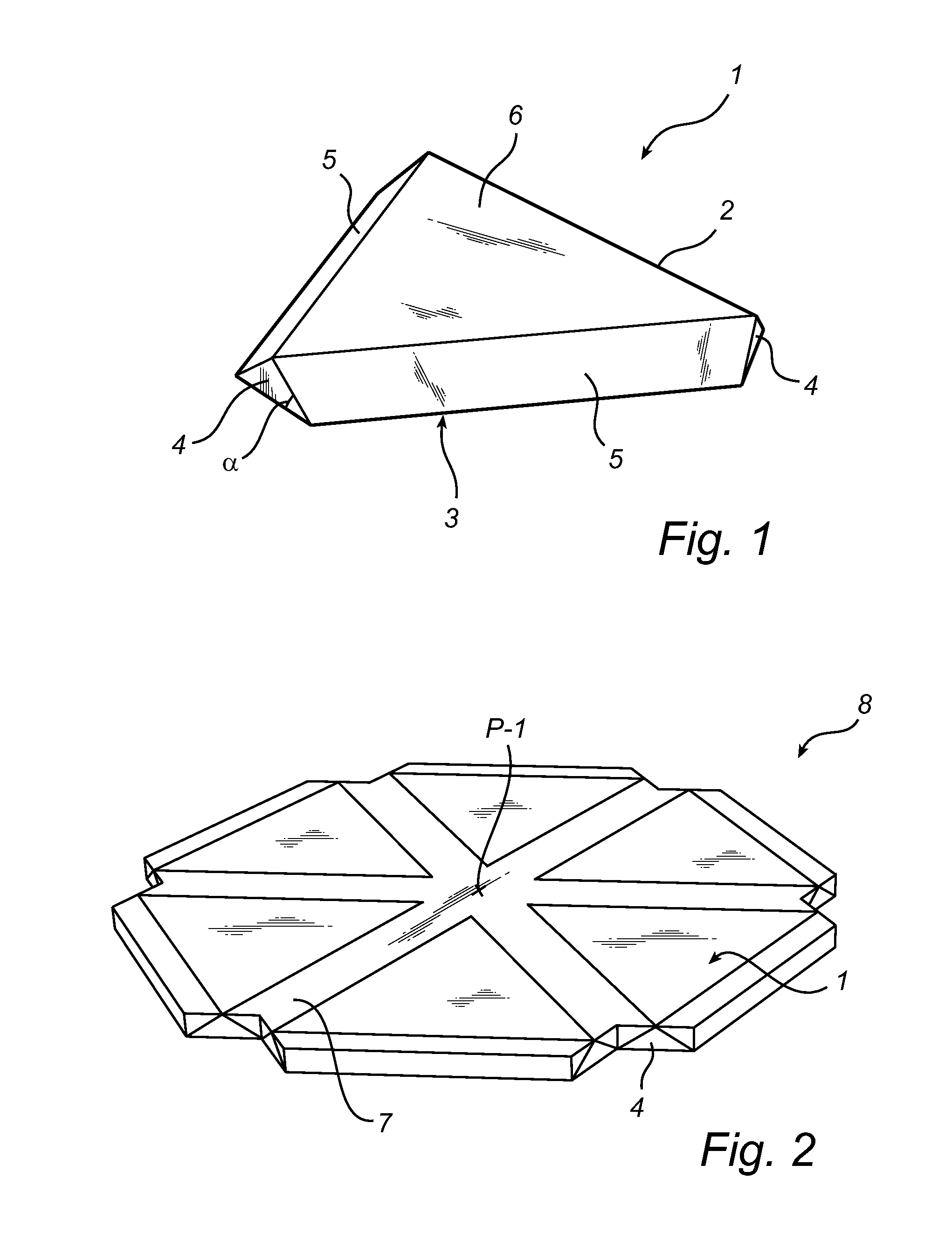
[0034]With reference to FIG. 1, a light guide 1 is shown. The light guide 1 has the shape of an equilateral triangle 2 and has a planar light emitting surface 3, a planar top surface 6, three light in-coupling corners 4 and three slanting sides 5, each defining a redirecting surface. Each slanting side defines an acute angle α with the light emitting surface 3. The acute angle can for instance be between 30° and 65°. The in-coupling corners 4 are arranged to allow in-coupling of light into the light guide, and are here formed as flat surfaces, i.e. as truncated corners.

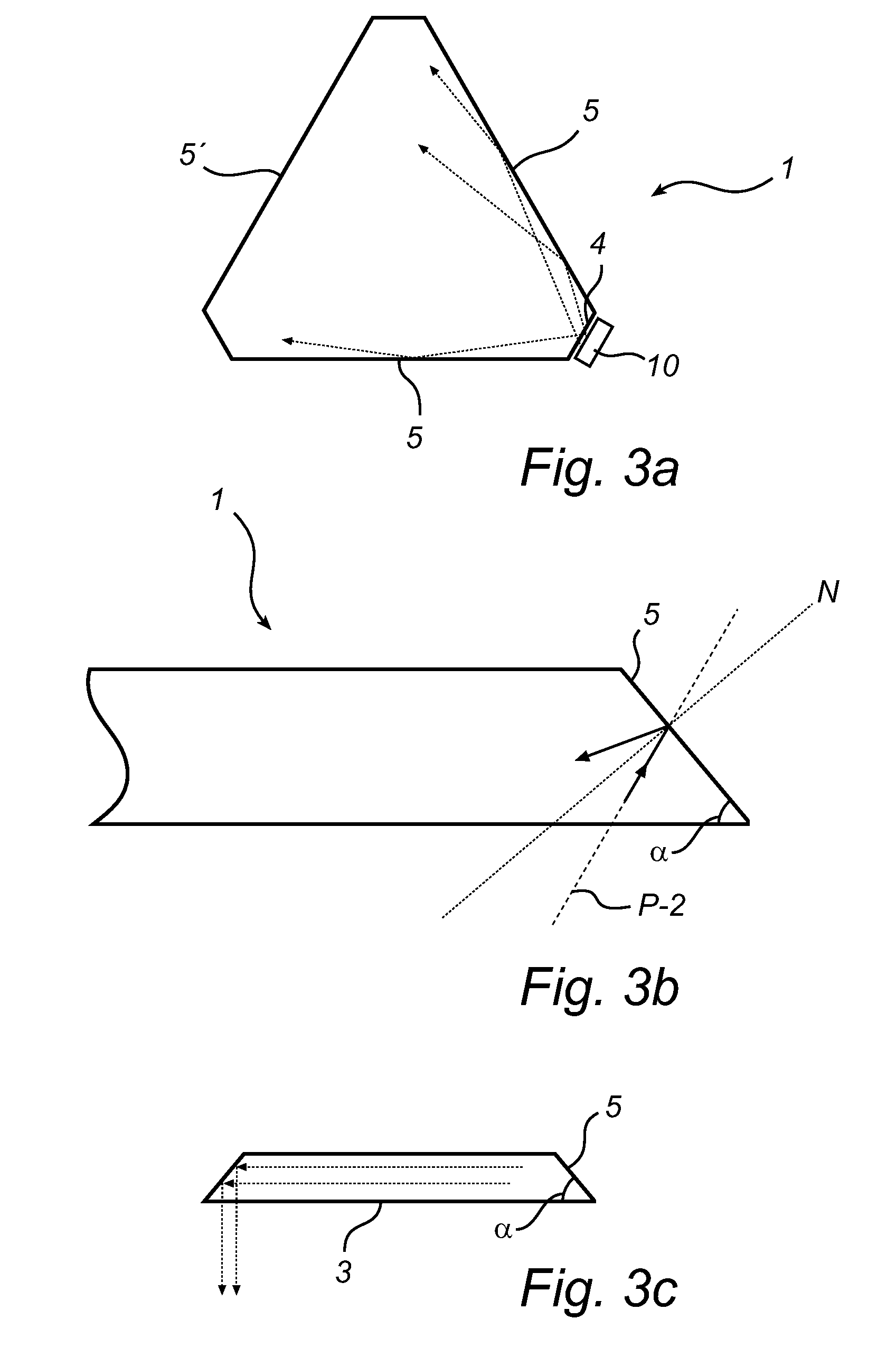
[0035]By placing an LED 10 (see FIG. 3a) adjacent a corner 4, light can be in-coupled into the light guide 1. In-coupled light is collimated and redirected in the light guide 1, via the two adjacent slanting sides 5, towards the slanting side 5 opposite the in-coupling corner 4. When the opposite slanting side 5 receives the collimated light it redirects light towards the planar light emitting surface 3. In FIGS. 3a-c...

second embodiment

[0055]FIG. 4 shows the light guide 1 according to the invention. The functioning of the present embodiment of the light guide 1 is the same as described hereabove. However, the in-coupling corners 4 are tapered to improve collimation in the light guide 1.

[0056]As each adjacent slanting side 5 of the equilateral triangle converge to a corner 4, the planar light emitting surface 3 and a planar top surface 6 start to converge towards each other. The top surface 6 and the light emitting surface 3 converge towards each other until intersecting a surface 11 formed between two adjacent slanting sides 5, which surface 11 defines the in-coupling corner 4. A tapered in-coupling corner 4 is hence formed. Thus, when light is in-coupled via the corner 4, there are four inclined collimating surfaces, each providing collimation parallel and transverse with the planar light emitting surface 3.

[0057]FIG. 5 shows a further embodiment of the light guide 1. Generally, the functioning of light guide 1 i...


PUM


Abstract

It is presented a light guide (1) having a polygonal shape with a plurality of sides (5), each side (5) connected by two corners (5). At least one of the corners is an in-coupling corner (4) for in-coupling of light into the light guide (1). At least one of the sides (5) has is slanting and collimates light in-coupled from an adjacent light in-coupling corner (4). The slanting side (5) can also reflect light towards a planar light emitting surface (3) for out-coupling of light therethrough. The light in-coupled in a light in-coupling corner (4) is collimated as if the light guide (1) is an equilateral triangle (2) having three slanting sides.

Description

FIELD OF THE INVENTION[0001]The technical field of the invention is lighting. In particular, the present invention relates to a light guide and a luminaire comprising such a light guide.BACKGROUND OF THE INVENTION[0002]The rapid development of solid state light sources over the last decade anticipates a large-scale use of Light Emitting Diodes (abbreviated LED) for general illumination. In particular, the increase in the amount of light (lumens—abbreviated lm) per package, the higher efficiency (lm / W), as well as the continuous decrease of the cost (lm / dollar) for LED sources, lead to the prediction that over the next several years LED lighting will be introduced on a large scale in the general illumination market.[0003]Light systems using LED's can benefit from several advantages over conventional fluorescent luminaries, while having similar or better efficiencies. These include fundamental properties like lifetime, but also a better flexibility in terms of sizes and shapes for the...

Claims


Application Information

Patent Timeline
Patent Type & Authority Applications(United States)
IPC IPC(8): G02B6/26
CPCG02B6/0078G02B6/002
Inventor ONAC, GABRIEL-EUGENVISSENBERG, MICHEL CORNELIS JOSEPHUS MARIE
Owner KONINKLIJKE PHILIPS ELECTRONICS NV
Why Eureka
Try Eureka