
Apparatus and method for performing line analysis of continuous data signals

a continuous data and optical line analysis technology, applied in the direction of electrical equipment, electrical transmission, transmission monitoring, etc., can solve the problems of inability to accurately measure the quality of the input signal, the optical line analysis of the signal cannot be performed on the signal that is not fully recovered, and the inability to perform conventional techniques for detecting the errors in the received signal

Active Publication Date: 2012-04-19
AVAGO TECH INT SALES PTE LTD
View PDF1 Cites 0 Cited by
  • Summary
  • Abstract
  • Description
  • Claims
  • Application Information

AI Technical Summary

Benefits of technology

Enables effective optical line analysis and supervision in PONs, allowing for efficient operation and maintenance by identifying and diagnosing issues before signal recovery, thereby improving network performance and reducing unnecessary technician dispatches.

Problems solved by technology

Thus a typical PON suffers from optical aberrations influencing the signals.
However, during the recovery process, essential information, such as eye distortion, frequency movement, phase information, jitter, and other effects are discarded, and thus the quality of the input signal cannot be correctly measured.
Optical line analysis of signals can be performed only on signals that are not fully recovered and cannot be performed using conventional techniques for detecting the errors in the received signals.

Method used


Image

  • Apparatus and method for performing line analysis of continuous data signals
  • Apparatus and method for performing line analysis of continuous data signals
  • Apparatus and method for performing line analysis of continuous data signals

Examples


Embodiment Construction

[0019]The embodiments disclosed herein are only examples of the many possible advantageous uses and implementations of the innovative teachings presented herein. In general, statements made in the specification of the present application do not necessarily limit any of the various claimed inventions. Moreover, some statements may apply to some inventive features but not to others. In general, unless otherwise indicated, singular elements may be in plural and vice versa with no loss of generality. In the drawings, like numerals refer to like parts through several views.

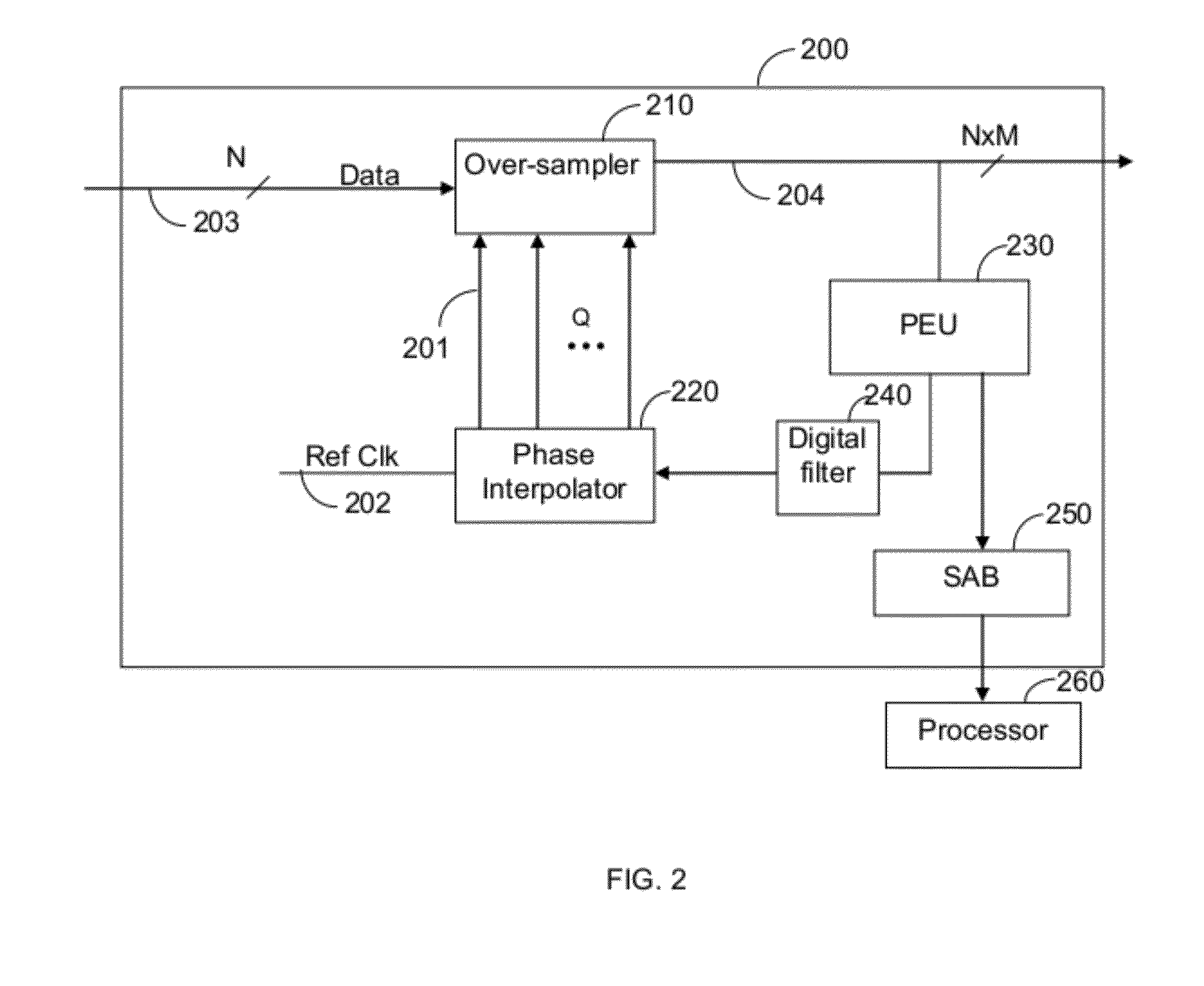
[0020]FIG. 2 shows a non-limiting block diagram of a CDR circuit 200 used to describe certain embodiments. The CDR circuit 200 is based on an over-sampling technique and includes an over-sampler 210, a phase interpolator 220, a phase estimation unit (PEU) 230, a digital filter 240, a statistical accumulation block (SAB) 250, and a processor 260. The phase interpolator 220 is used to generate a number Q (where Q is an i...


PUM


Abstract

A method for performing an optical line analysis of continuous data signals transmitted in a passive optical network (PON). The method comprises determining, from an optical signal of the optical line, at least one of a phase early / late indicator based on a phase position of an input continuous data signal relative to sampling clock signals, a difference phase indicator based on an input phase control code, and a low frequency jitter indicator based on an input phase control code; computing a plurality of statistical measures regarding frequency and amplitude components of a jitter of the input continuous data signal, wherein the statistical measures are computed based on one of the phase early / late information indicator, the difference phase indicator, and the low frequency jitter indicator; and analyzing the plurality of statistical measures to detect optical failures in the PON and determining a root cause of each of the detected failures.

Description

CROSS-REFERENCE TO RELATED APPLICATIONS[0001]This application is a continuation of U.S. patent application Ser. No. 12 / 434,051 filed May 1, 2009, now allowed, which claims the benefit of U.S. Provisional Application No. 61 / 049,771 filed on May 2, 2008, the contents of which are herein incorporated by reference.TECHNICAL FIELD[0002]The present invention relates generally to an apparatus and a method for measurement of the quality of signals transmitted in optical transmission systems.BACKGROUND OF THE INVENTION[0003]Many communication networks that provide high bit-rate transport over a shared medium are characterized by non-continuous, or burst mode, data transmission in the upstream direction and continuous data transmission in the downstream direction. An example of such a network is a passive optical network (PON) 100 schematically shown in FIG. 1. A typical PON 100 includes a plurality of optical network units (ONUs) 120-1 through 120-M coupled to an optical line terminal (OLT) ...

Claims


Application Information

Patent Timeline
Patent Type & Authority Applications(United States)
IPC IPC(8): H04B17/00H04B10/00
CPCH04B10/0795
Inventor DVIR, AMIADGOLDSTEIN, ALEXAVISHAI, DAVID
Owner AVAGO TECH INT SALES PTE LTD
Features
  • Generate Ideas
  • Intellectual Property
  • Life Sciences
  • Materials
  • Tech Scout
  • Unparalleled Data Quality
  • Higher Quality Content
  • 60% Fewer Hallucinations
Learn More