Grind-stone-mount of honing head

a honing head and grinding stone technology, which is applied in the field of grinding stone mounts of honing heads, can solve the problems of unavoidable shape of bores attained after honing, engine may not be able to exhibit desired performance, and large deformation of bores, so as to achieve smooth follow the inside shape

Inactive Publication Date: 2012-04-19
HONDA MOTOR CO LTD
View PDF8 Cites 3 Cited by
  • Summary
  • Abstract
  • Description
  • Claims
  • Application Information

AI Technical Summary

Benefits of technology

[0025]When the structure of any of the embodiments of the invention is employed, the contact pressure of the grind stone may be kept substantially constant by the spring member, and in addition, the grind part may be swung in regard to the support part with the spring member used as a fulcrum. Therefore, the grind stone may be made to smoothly follow the inside shape of a is hole of a workpiece even in a portion shifted from a direction parallel to the axial direction, and hence, the honing (including rough machining and surface finishing) may be performed while keeping the original inside shape of the hole.

Problems solved by technology

Such deformation of the bore may be a factor to increase slide resistance between the bore and the piston caused in use of the engine, and it is apprehended that the engine may not be able to exhibit desired performance.
However, when the dummy head or the like is attached and removed every time the bore of the cylinder head is worked, there arises a problem that the productivity is largely degraded.
However, a grind-stone-mount of a conventional honing head used in the honing is made of a metal and is not deformable.
As a result, the shape of the bore attained after completing the honing is unavoidably in a state close to a shape of a circular cross section again from the shape of the non-circular cross section obtained through the boring.

Method used


Image

  • Grind-stone-mount of honing head
  • Grind-stone-mount of honing head
  • Grind-stone-mount of honing head

Examples


Embodiment Construction

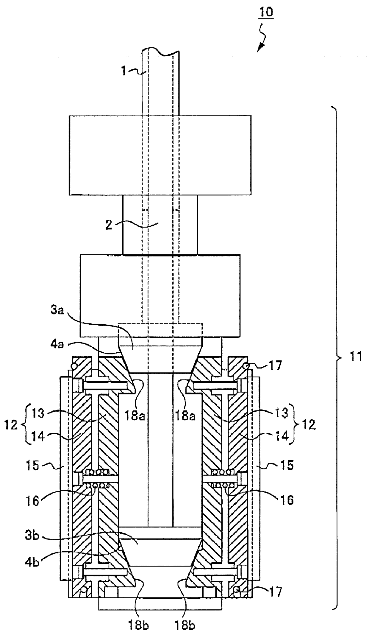
[0030]Exemplary embodiments of the invention will be described with reference to the accompanying drawings. FIG. 1 is a schematic vertical cross-sectional view of a honing head 10 including a grind-stone-mount 12 according to a first exemplary embodiment of the invention.

[0031]As illustrated in FIG. 1, the honing head 10 is removably attached, for use, to a lower end portion of a spindle 1 rotatably and vertically movably provided on a honing machine (not shown).

[0032]The honing head 10 includes a substantially cylindrical holder 11 attached to the lower end portion of the spindle 1 and a plurality of grind-stone-mounts 12 respectively disposed in a plurality of slits formed at prescribed intervals along a circumferential direction of the holder 11. In FIG. 1, merely two grind-stone-mounts 12 disposed to oppose each other are illustrated.

[0033]The grind-stone-mounts 12 are attached to the holder 11 to be expandable along radial directions (namely, along directions away from the cent...


PUM


Abstract

A plurality of grind-stone-mounts 12 each having a grind stone 15 on its outer side are attached to a holder 11 of a honing head 10 expandably along a radial direction. Each of the grind-stone-mounts 12 is provided with a support part 13 disposed inside along the radial direction, and a grind part 14 including the grind stone 15 and disposed outside along the radial direction. The grind part 14 is swingably attached to the support part 13 through one or more spring members 16 disposed at intervals along an axial direction of the holder 11.

Description

TECHNICAL FIELD[0001]The present invention relates to a grind-stone-mount of a honing head. More specifically, it relates to a grind-stone-mount of a honing head used for honing of an inside diameter of a hole in a shape of a non-circular cross section formed in a workpiece.BACKGROUND ART[0002]In a production process for automobiles, bores of cylinder blocks of engines are cut, and thereafter, cylinder heads and crank cases are assembled on the cylinder blocks. Since a piston to be placed in a bore is in a shape of a circular cross section, the bore is cut so as to attain a state where its cross section is close to a true circle.[0003]However, even if each bore of the cylinder block is cut into a shape of a circular cross section, when the cylinder head, the crank case and the like are assembled to the cylinder block, the shape of the bore is deformed. Such deformation of the bore may be a factor to increase slide resistance between the bore and the piston caused in use of the engin...

Claims


Application Information

Patent Timeline
Patent Type & Authority Applications(United States)
IPC IPC(8): B24B55/00
CPCB24B33/08
Inventor SOGAWA, KAZUSHIFUJIWARA, HIDEOKODAMA, KAZUYAFUKUMITSU, JIN
Owner HONDA MOTOR CO LTD
Why Eureka
Try Eureka