Position sensor for throttle body

A throttle body and sensor technology, applied in the field of sensors, can solve problems such as inability to guarantee constant contact pressure and output voltage stability

Inactive Publication Date: 2011-09-07
SHANGHAI AUZONE AUTO PARTS MFG CO LTD
View PDF4 Cites 2 Cited by
  • Summary
  • Abstract
  • Description
  • Claims
  • Application Information

AI Technical Summary

Problems solved by technology

The resistance of the existing throttle position sensor is coated on the film, and the film is not placed on the top but close to the inner wall along the inner cavity of the plastic shell. The film is relatively soft and cannot guarantee constant contact pressure and output voltage stability.

Method used


Image

  • Position sensor for throttle body
  • Position sensor for throttle body
  • Position sensor for throttle body

Examples


Embodiment Construction

[0014] A preferred embodiment will be given below, and the present invention will be described more clearly and completely in conjunction with the accompanying drawings.

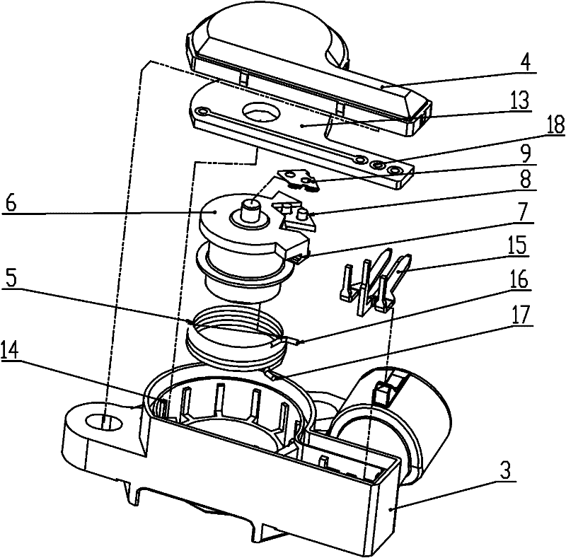
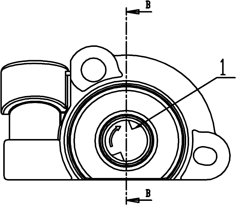
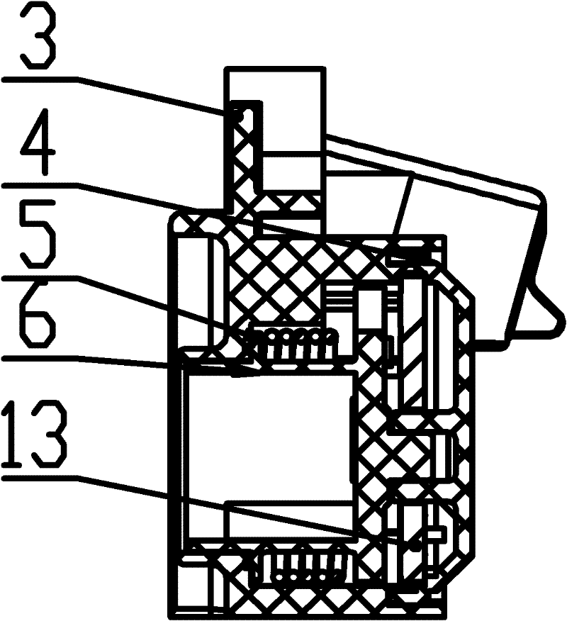
[0015] Such as Figure 1 to Figure 5 As shown, the throttle body position sensor of the present invention includes a plastic housing 3, a cover 4, a return spring 5, a brush body 6, a brush 9, a PCB substrate 13, a pillar 8, a mechanical top dead center 12, and a mechanical bottom dead center 11. The first hanging pin 7, the second hanging pin 10 and the pin 15. Pillar 8 is protruding outwards. The seal between the cover 4 and the plastic shell 3 is connected by glue. The brush main body 6 is inserted into the hole of the plastic housing 3 and is clearance-fitted with the plastic housing 3 . The electric brush 9 is connected with the post 8 with interference, and the reverse barb on the electric brush 9 is stuck on the post 8 to prevent falling off. A torsion arm 16 of the back-moving spring 5 is hung on...


PUM


Abstract

The invention discloses a position sensor for a throttle body. The position sensor for the throttle body comprises a plastic shell, a sealing cover, a return spring, an electric brush main body, an electric brush, a print circuit board (PCB) substrate, a post, a first hanging foot and a second hanging foot. The sealing cover and the plastic shell are sealed and connected in a bonding way; the electric brush main body is inserted into a hole of the plastic shell and is in clearance fit with the plastic shell; the electric brush is in clearance fit with the post; one torsion arm of the return spring is hung on the first hanging foot, and the other torsion arm of the return spring is hung on the second hanging foot; and the PCB substrate is arranged on one side of the plastic shell and pressed against the upper part of the electric brush main body. The PCB substrate is pressed against the upper part of the electric brush main body and keeps a certain distance with the electric brush; and the electric brush is always tightly attached to a resistive layer of the PCB substrate, so that a constant contact pressure is kept and the stability of an output voltage is ensured.

Description

technical field [0001] The invention relates to a sensor, in particular to a throttle body position sensor. Background technique [0002] The throttle position sensor (Throttle Position Sensor, TPS) is installed on one end of the throttle shaft on the throttle body, and its function is to convert the throttle opening (that is, the engine load) into an electrical signal and then input it to the ECU (Electronic Control Unit, Electronic control unit), the ECU judges the working conditions of the engine according to the throttle position signal, such as idle speed working conditions, partial load working conditions, heavy load working conditions, etc., and controls the fuel injection time according to the requirements of the mixed gas concentration in different working conditions of the engine . The resistance of the existing throttle position sensor is coated on the film, and the film is not placed on the top but is closely attached to the inner wall along the inner cavity of ...

Claims


Application Information

Patent Timeline
Patent Type & Authority Applications(China)
IPC IPC(8): G01D5/165
Inventor 戴益锋
Owner SHANGHAI AUZONE AUTO PARTS MFG CO LTD
Why Eureka
Try Eureka