Floor cleaning apparatus employing a combined sweeper and vaccum assembly

a floor cleaning and vaccum assembly technology, applied in the direction of vacuum cleaners, floor sweeping machines, carpet cleaners, etc., can solve the problems of clogging internal vacuum components, noisy prior art apparatus, and insufficient vacuum

Inactive Publication Date: 2012-04-26
KARCHER NORTH AMERICA INC
View PDF6 Cites 20 Cited by
  • Summary
  • Abstract
  • Description
  • Claims
  • Application Information

AI Technical Summary

Benefits of technology

[0013]It is one aspect of the present invention to provide a floor cleaning apparatus (“apparatus”) that employs a scrubber and sweeper assembly (hereinafter “cleaning assembly”). The cleaning assembly includes a front brush and a rear brush that are partially enclosed by a housing that, with the aid of a vacuum motor, directs air between the front brush and the second brush and into a hopper. The suction provided by the vacuum motor directs particle- and debris-laden air into the hopper wherein sm

Problems solved by technology

Further, the prior art apparatus are noisy and do not provide a sufficient vacuum.
Another drawback is that the prio

Method used


Image

  • Floor cleaning apparatus employing a combined sweeper and vaccum assembly
  • Floor cleaning apparatus employing a combined sweeper and vaccum assembly
  • Floor cleaning apparatus employing a combined sweeper and vaccum assembly

Examples


Embodiment Construction

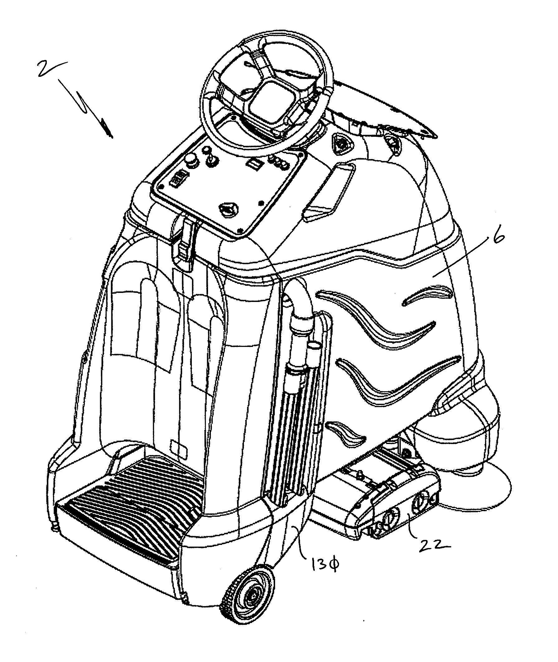
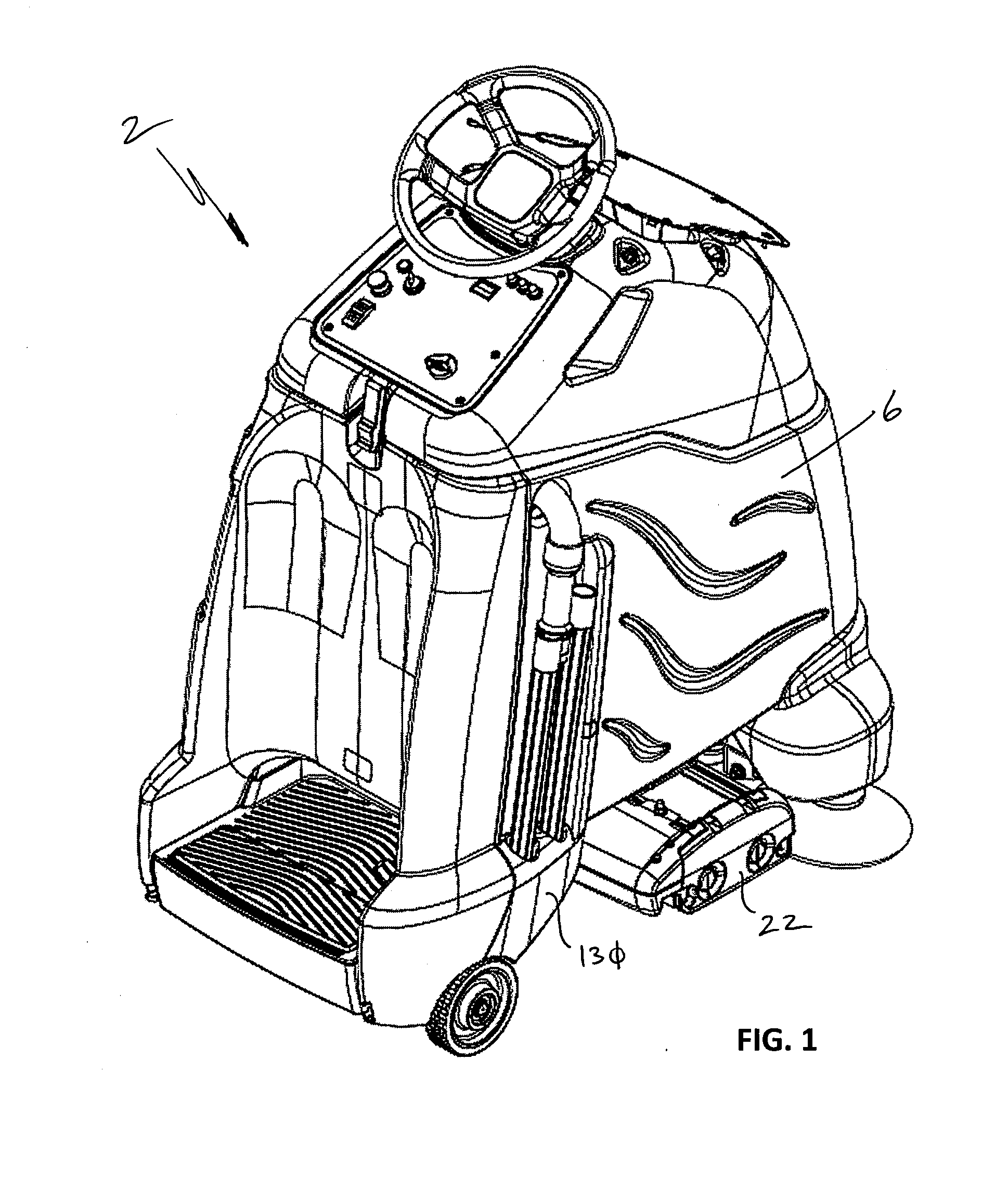
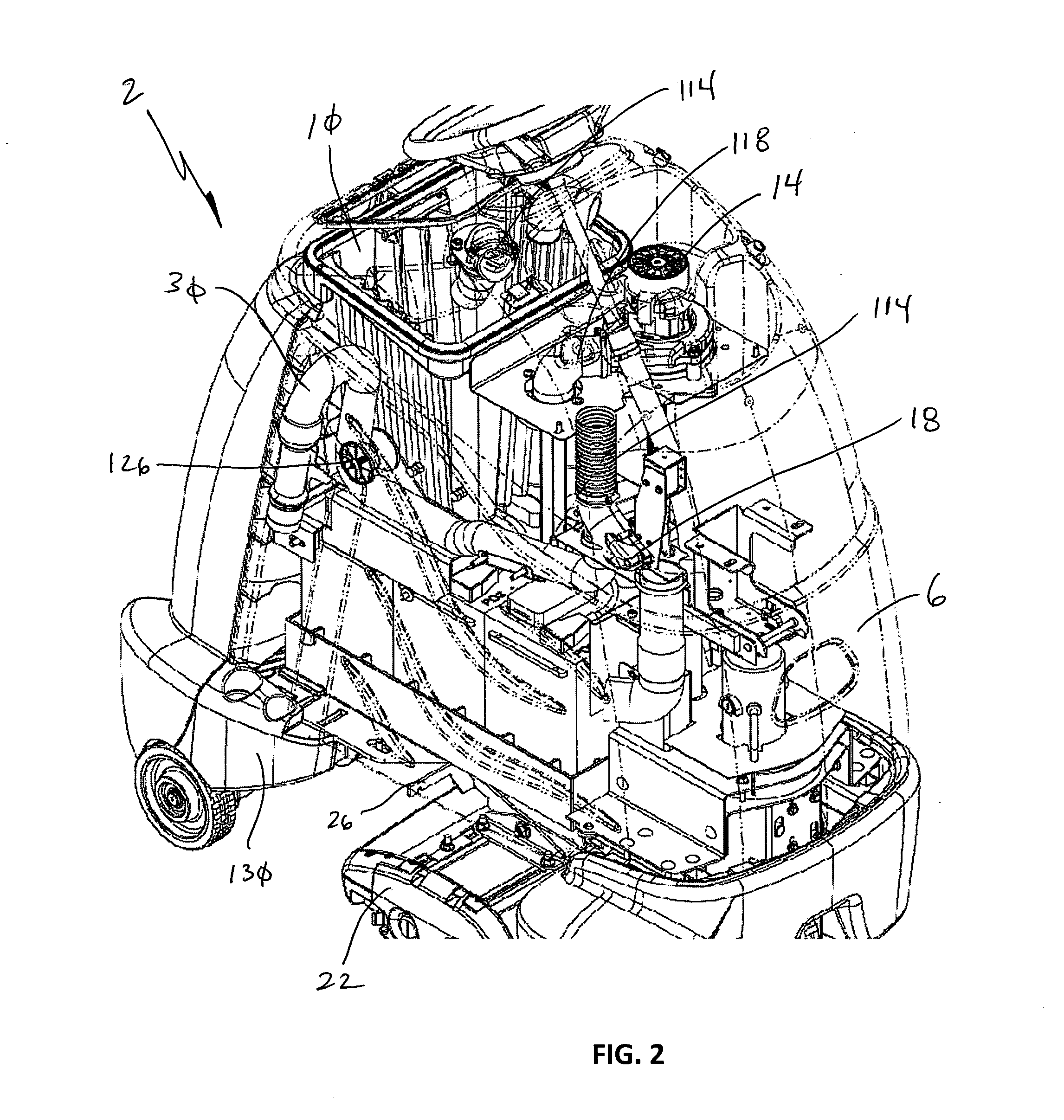
[0040]FIGS. 1-3 show a scrubber / sweeper apparatus 2 (hereinafter “apparatus”) of one embodiment of the present invention that employs a housing 6 that covers a vacuum bag 10, a vacuum motor 14, a valve 18, and other components generally found in floor cleaning apparatus. In addition, the apparatus 2 employs a cleaning assembly 22 that is attached to the housing 6 via a spring to an armature 26, which will be further described below. In operation, dirt, debris, and residue are agitated by the cleaning assembly 22 and suctioned into the vacuum bag 10. In a second mode of operation, a hand-held accessory hose 30 is used to suction debris in hard-to-reach places. The debris suctioned through the accessory hose 30 is also directed to the vacuum bag 10 by the vacuum motor 14.

[0041]Referring now specifically to FIGS. 4-7, the cleaning assembly 22 employed by some embodiments of the present invention is shown that includes a front brush 34 and a rear brush 38. The front brush 34 and rear br...


PUM


Abstract

A floor cleaning device employing a brush assembly is provided. The brush assembly includes a front brush and a rear brush that spin about an axis line generally parallel to the surface being cleaned. The spinning rotation of the brush along with the configuration of the housing help provide an airflow path that sucks debris from the surface being cleaned. The debris is directed to a hopper wherein larger items are captured and smaller items are suctioned into a vacuum bag.

Description

[0001]This application is related to U.S. Pat. Nos. 5,555,596, entitled “Floor Cleaning Apparatus”; 5,485,653, entitled “Floor Cleaning Apparatus”; 5,628,086, entitled “Floor Cleaning Apparatus with Squeegee Mounting System”; and 5,608,947, entitled “Floor Cleaning Apparatus With Pre-Filter”; the entire disclosures of which are incorporated by reference herein. This application is also related to U.S. patent application Ser. No. 11 / 059,663, filed Feb. 15, 2005, now U.S. Pat. No. 7,533,435, which is a Continuation-In-Part of U.S. patent application Ser. No. 10 / 737,027, filed Dec. 15, 2003, now abandoned, which is a Continuation-In-Part of U.S. patent application Ser. No. 10 / 438,485, filed May 14, 2003, now abandoned, the entire disclosures of which are incorporated by reference in their entirety herein. This application is also related to U.S. Patent Application Publication Nos. 2009 / 0094784, 2006 / 0064844, 2006 / 0124770, and 2006 / 0156498, and U.S. patent application Ser. No. 12 / 511,70...

Claims


Application Information

Patent Timeline
IPC IPC(8): A47L9/00
CPCA47L11/24A47L11/4027A47L11/4066A47L11/4044A47L11/4041
Inventor VENARD, DANIEL C.HEIN, ROBINPYNE, SCOTT JOSEPH
Owner KARCHER NORTH AMERICA INC
Why Eureka
Try Eureka