
Method of Applying Abrasion Resistant Materials to Rotors

a technology rotors, applied in the field of abrasion resistance materials, can solve the problems of rotors that rotate at high speed and experience substantial wear, elastomeric delamination within the polymeric coating of the rotor, and rotors to fail

Inactive Publication Date: 2012-04-26
TEXTRON INNOVATIONS
View PDF11 Cites 3 Cited by
  • Summary
  • Abstract
  • Description
  • Claims
  • Application Information

AI Technical Summary

Benefits of technology

[0049]The process of the present application provides significant advantages, including: (1) handling and shipping costs are reduced; (2) substantial time and effort is no longer exhausted through the upgrading process; (3) different coatings are applied without having to change any forming or cutting tooling; and (4) the worker can perform the application process in the field.

Problems solved by technology

During operation, rotors rotate at high velocities and experience substantial wear due to particulate matter, i.e., water and sand, hitting the surface of the rotor.
For example, water spheres exert high impact forces against the rotor which can result in elastomeric delaminating within the polymeric coating of the rotor.
In addition, the water spheres can form micro-cracks on metal that can propagate together to form macro-cracks, thereby causing the rotors to fail.
The shields provide an inexpensive solution for adding additional abrasion and erosion resistance, but have been found to be ineffective as a means for reducing wear.
The coating thickness of the abrasion resistant material is not uniform, resulting in considerable post-process upgrade work, such as grinding to make the rotor aerodynamically satisfactory.
There is also a need to ship the rotors to the plating facility, as plating lines cannot be moved to where the aircraft is located.
As a result, disassembly, handling, and shipping costs accrue.
In addition, the rotors must be shipped to the facility, resulting in disassembly, handling, and shipping costs.
In both cases, there is a considerable effort and time invested in forming, grinding, polishing, and bonding in order to arrive at the finished product.
Both electroplating and electroforming process are slow, difficult to control, complex in nature, and limited with regard to suppliers of services and raw materials.

Method used


Image

  • Method of Applying Abrasion Resistant Materials to Rotors
  • Method of Applying Abrasion Resistant Materials to Rotors
  • Method of Applying Abrasion Resistant Materials to Rotors

Examples


Embodiment Construction

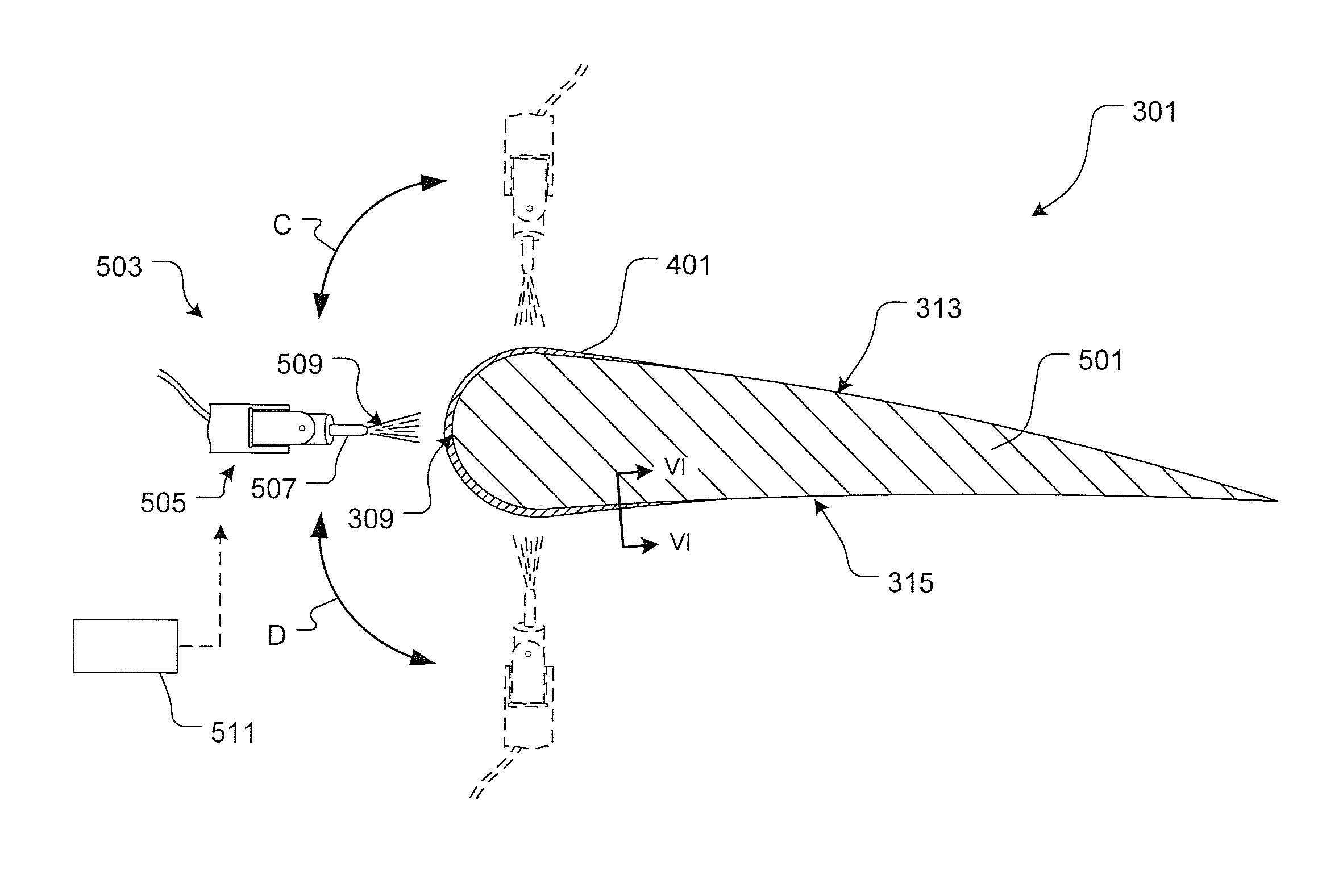
[0019]The process for applying an abrasion resistant material to a rotor of the present application overcomes the disadvantages of conventional techniques for applying abrasion resistant materials to rotors. Illustrative embodiments are described below. It will of course be appreciated that in the development of any actual embodiment, numerous implementation-specific decisions will be made to achieve the developer's specific goals, such as compliance with system-related and business-related constraints, which will vary from one implementation to another. Moreover, it will be appreciated that such a development effort might be complex and time-consuming, but would nevertheless be a routine undertaking for those of ordinary skill in the art having the benefit of this disclosure.

[0020]The present application is directed to a process for applying abrasion resistant materials to a rotor. The abrasion resistant material is thermally sprayed onto the rotor either through a manual or by an ...


PUM

PropertyMeasurementUnit
temperatureaaaaaaaaaa
thicknessaaaaaaaaaa
abrasion resistantaaaaaaaaaa

Abstract

A process for applying a plurality of coats of abrasion resistant material to a substrate such as a rotor for an air-craft. The abrasion resistant material is composed of a first and a second material. The coats gradually transition from an abrasion resistant composition having a larger percentage part per volume of the first material to a larger percentage part per volume of the second material as additional coats are applied.

Description

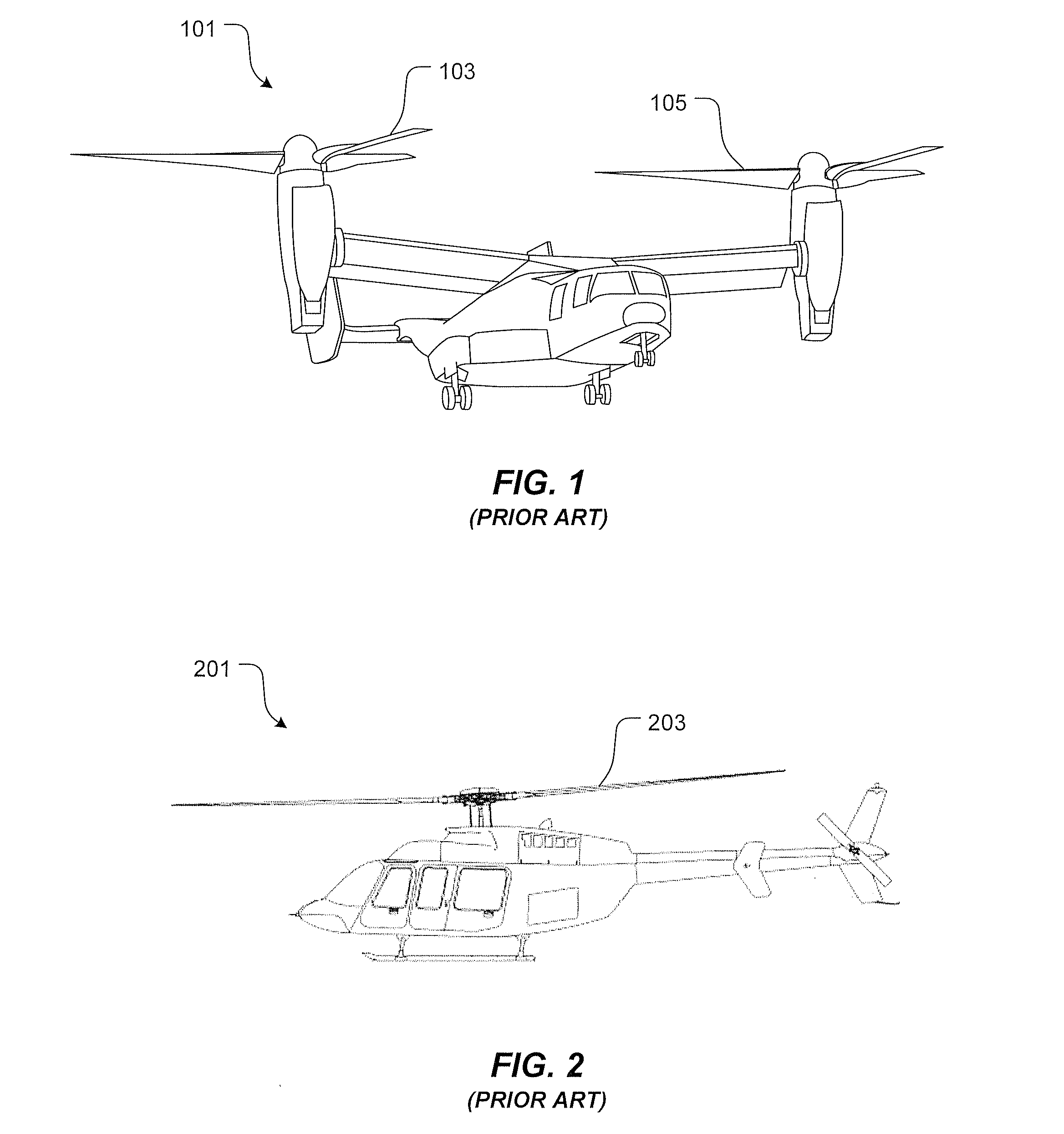
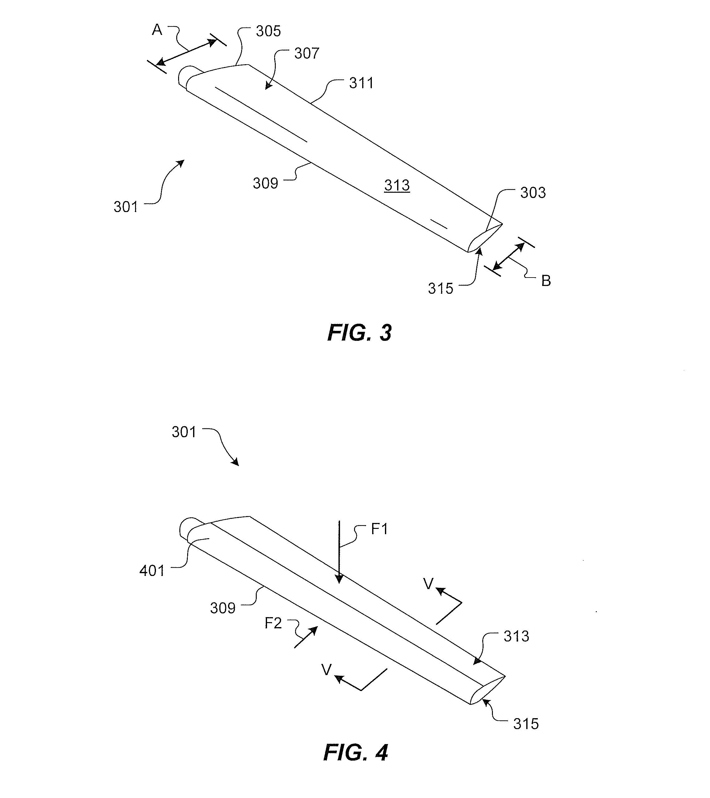
TECHNICAL FIELD[0001]The present application relates generally to the field of abrasion resistant materials and, more particularly, to a process for applying abrasion resistant materials to a substrate.DESCRIPTION OF THE PRIOR ART[0002]Rotors are well known in the art for effectively propelling various types of aircraft in flight. For example, FIG. 1 illustrates a conventional tiltrotor aircraft 101 propelled by two rotors 103 and 105, while FIG. 2 illustrates a conventional helicopter 201 propelled by rotor 203. Rotors come in various shapes, sizes and with different aerodynamic contouring for providing maximum propulsion. As is shown, rotors 103 and 105 have a shorter longitudinal length and a greater axial curvature than rotor 203. Like the majority of rotors, rotors 103, 105, and 203 are composed of sufficiently flexible materials for withstanding forces exerted against the rotor during flight. Typical rotor materials include metals, plastics, composites, wood, and other suitabl...

Claims


Application Information

Patent Timeline
Patent Type & Authority Applications(United States)
IPC IPC(8): B23P6/00B05D1/36B05D1/08
CPCC23C4/02F01D5/005F01D5/288Y02T50/672Y02T50/673Y10T29/49318F05D2230/30F05D2230/80F05D2230/31F05D2230/312F05D2230/90Y02T50/60
Inventor BISHOP, STEPHEN K.PEACH, GERALD
Owner TEXTRON INNOVATIONS
Learn More