System and Method for Inductive Signal and Power Transfer from ROV to In Riser Tools

a technology of inductive signal and power transfer, which is applied in the field of offshore drilling, can solve problems such as the inherent risk of damage to the umbilical cord

Active Publication Date: 2012-04-26
VETCO GRAY
View PDF25 Cites 33 Cited by
  • Summary
  • Abstract
  • Description
  • Claims
  • Application Information

AI Technical Summary

Problems solved by technology

This arrangement presents an obstacle to the use of a surface BOP for subsea completion operations as the spanner joint must be located at the surface location, resulting in a variable height ...

Method used


Image

  • System and Method for Inductive Signal and Power Transfer from ROV to In Riser Tools
  • System and Method for Inductive Signal and Power Transfer from ROV to In Riser Tools
  • System and Method for Inductive Signal and Power Transfer from ROV to In Riser Tools

Examples


Embodiment Construction

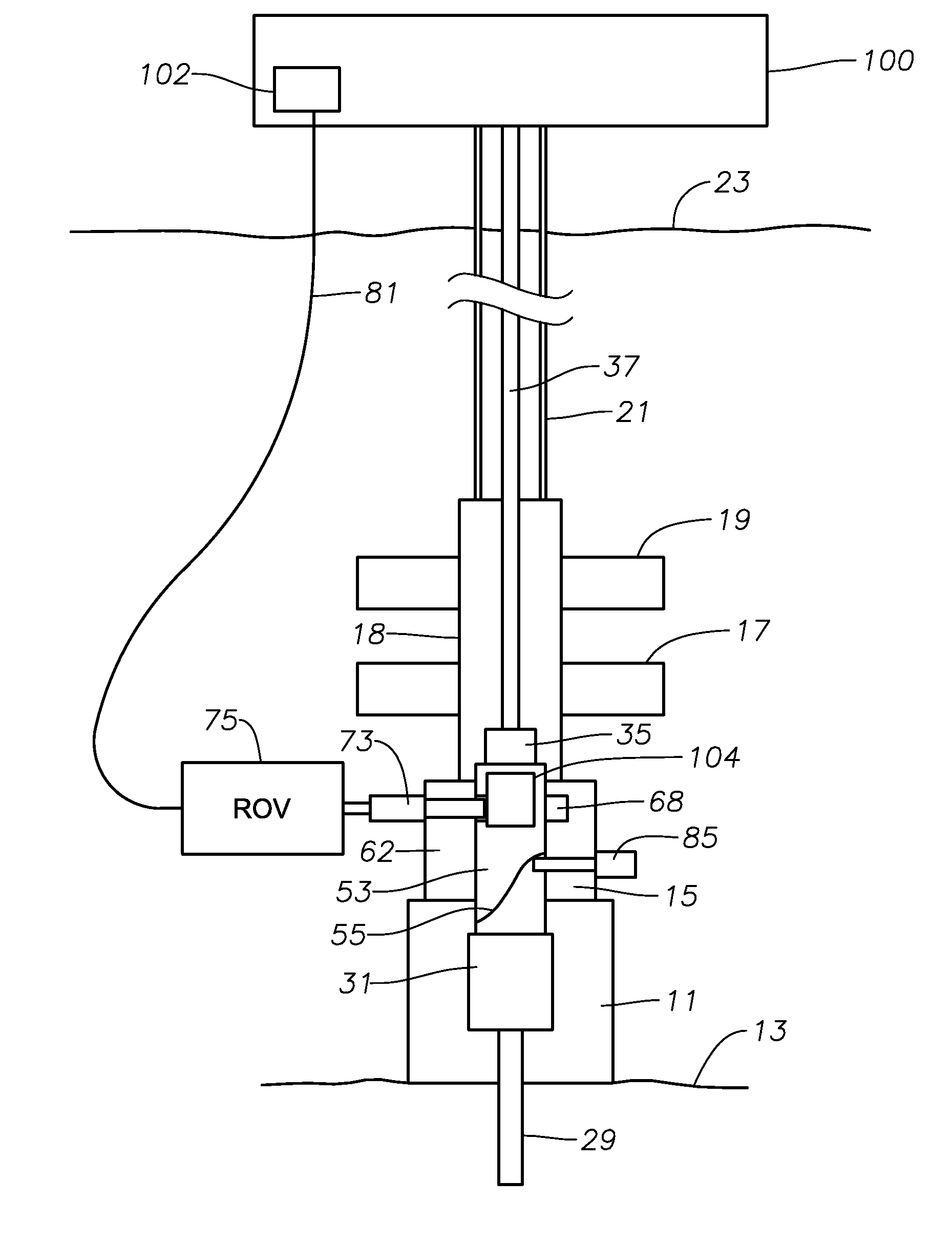
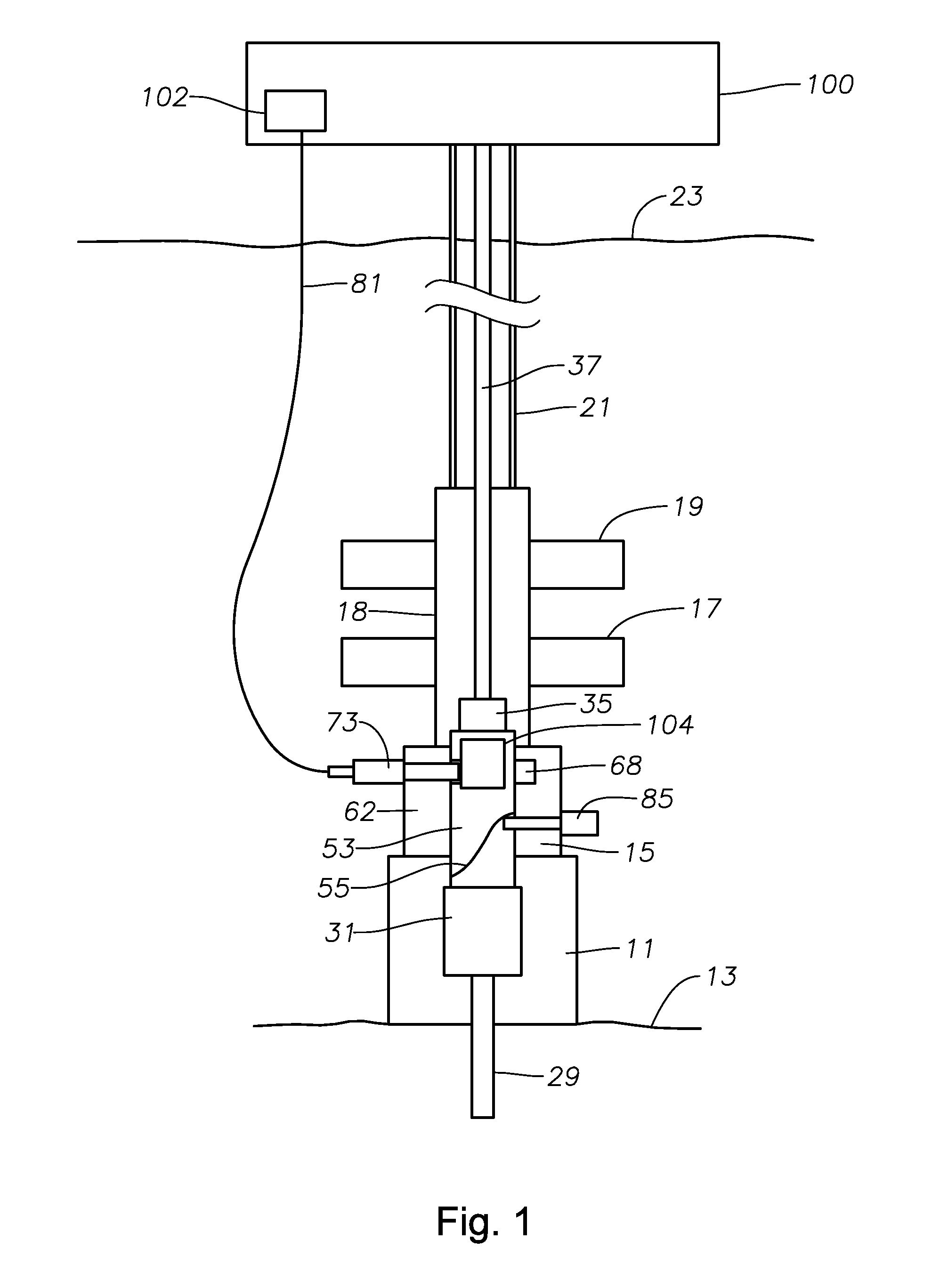
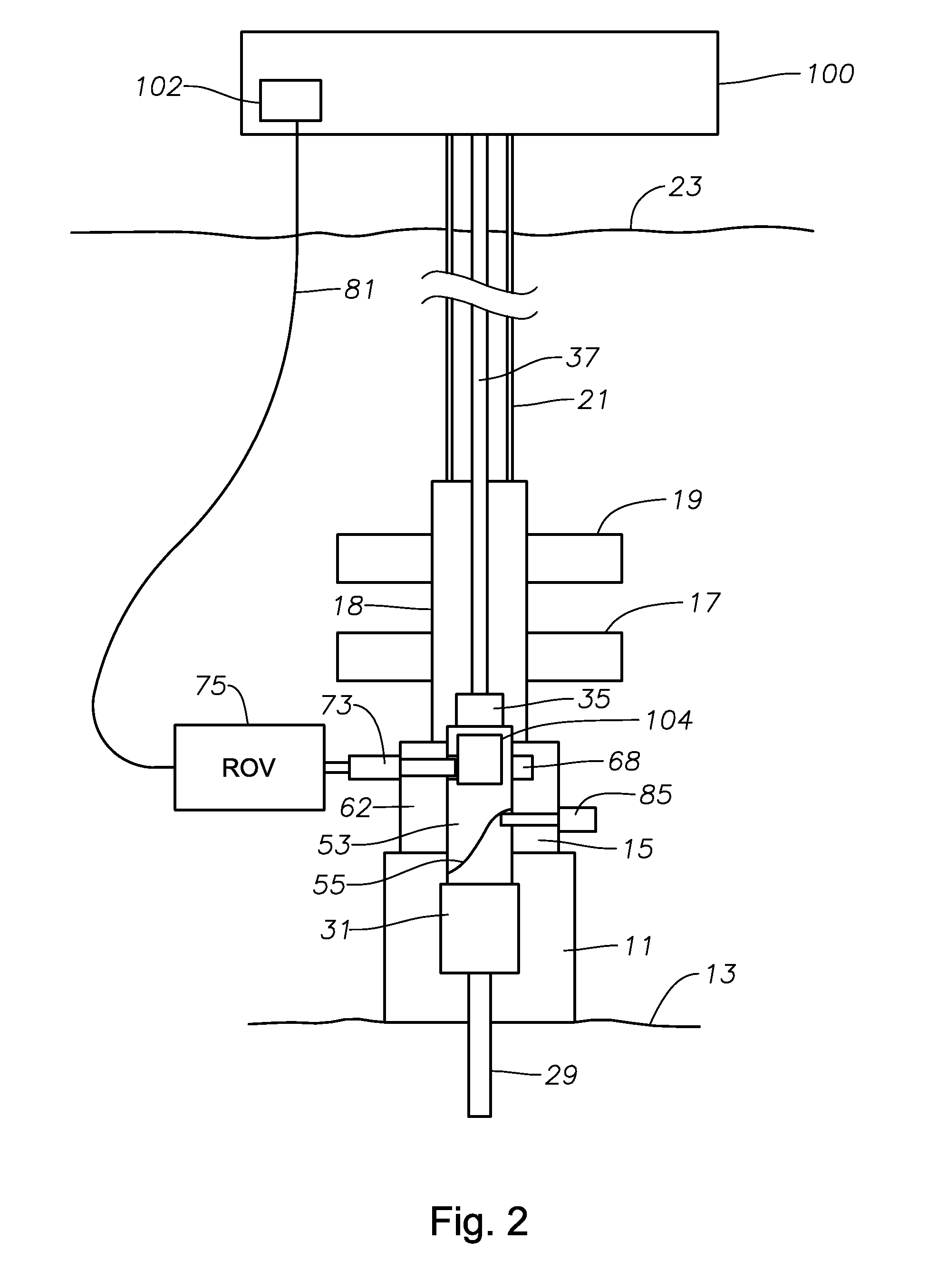
[0011]The present invention will now be described more fully hereinafter with reference to the accompanying drawings in which embodiments of the invention are shown. This invention may, however, be embodied in many different forms and should not be construed as limited to the illustrated embodiments set forth herein; rather, these embodiments are provided so that this disclosure will be thorough and complete, and will fully convey the scope of the invention to those skilled in the art. Like numbers refer to like elements throughout.

[0012]A subsea well assembly is described with reference to FIG. 1, where a wellhead 11 is schematically shown located at sea floor 13. Wellhead 11 may be a wellhead housing, a tubing hanger spool, or a Christmas tree of a type that supports a tubing hanger within. An adapter 15 connects wellhead 11 to a subsea blow-out preventer (BOP) 18, typically having a set of pipe rams 17. Pipe rams 17 seals around pipe of a designated size range but will not fully ...


PUM


Abstract

A subsea wellhead assembly having a completion landing string inside a drilling riser is described herein and comprises a power source for generating an alternating electrical current; a connector for connecting the power source to a receptacle in the subsea well assembly; a first inductor electrically connected to the power source through the connector; a subsea control module delivering power and control signals to the subsea well assembly; and a second inductor spaced from the first inductor, and located in the subsea control module, the second inductor positioned so that an EMF is produced on the second inductor when the alternating electrical current is passed through the first inductor to thereby generate an alternating current signal on the second inductor.

Description

BACKGROUND OF THE INVENTION[0001]1. Field of the Invention[0002]This invention relates in general to offshore drilling, and in particular to equipment and methods for providing electrical communication between a surface drilling platform or an ROV using an umbilical.[0003]2. Prior Art[0004]Control of subsea equipment is typically effected from the surface mounted control station via an umbilical. The umbilical typically carries hydraulic power and may include electrical power, and communication for control and monitoring of equipment in or on the well. When completing a subsea well for subsea production, a riser extends from a surface vessel and attaches to the subsea well. A tubing hanger is lowered on a conduit (typically termed a landing string) through the riser and landed in the tubing spool or wellhead assembly. A tubing hanger running tool, which is connected to the upper end of the tubing hanger sets the seal and locking member of landing of the tubing hanger in the wellhead...

Claims


Application Information

Patent Timeline
IPC IPC(8): E21B43/00
CPCE21B33/0385E21B33/0355E21B33/035E21B47/13
Inventor FENTON, STEPHEN P.
Owner VETCO GRAY
Why Eureka
Try Eureka