

Hydraulic power steering apparatus
a technology of hydraulic power steering and power steering device, which is applied in the direction of power steering, fluid steering, vehicle components, etc., can solve the problem of inability to change the assist force depending on various types of demands, and achieve the effect of improving flexibility
- Summary
- Abstract
- Description
- Claims
- Application Information
AI Technical Summary
Benefits of technology
Problems solved by technology
Method used
Image

Examples
first embodiment
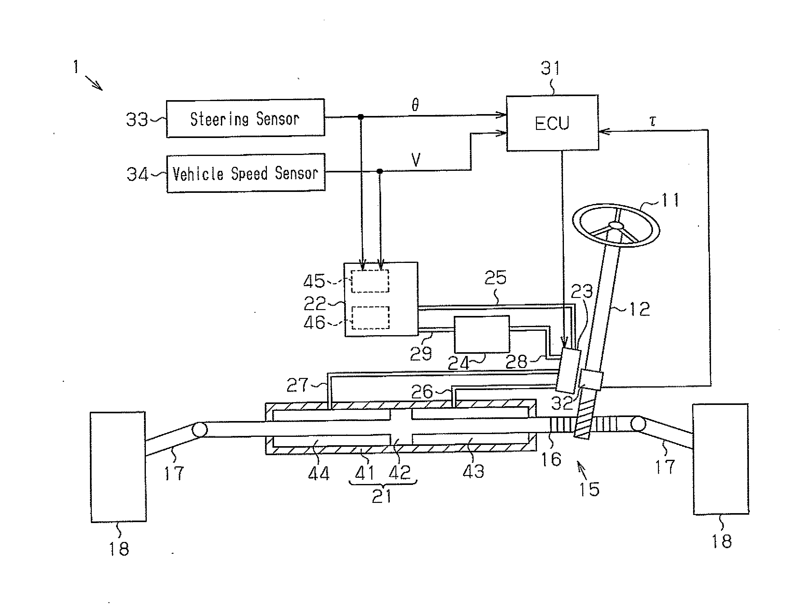
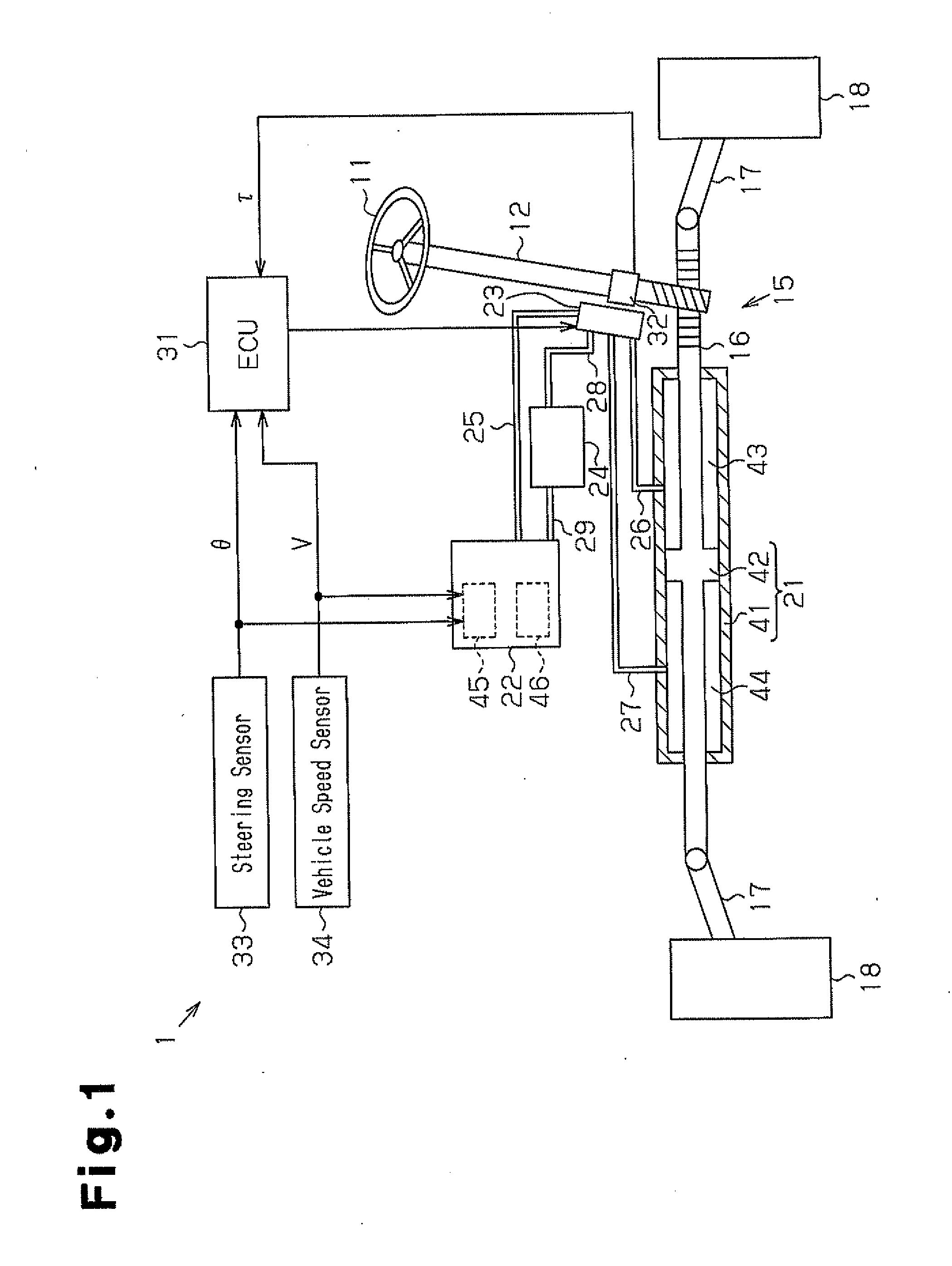
[0033]A hydraulic power steering apparatus 1 according to a first embodiment of the present invention will now be described with reference to FIGS. 1 to 5B.
[0034]As shown in FIG. 1, a steering wheel 11 is fixed to a steering shaft 12. A rack and pinion mechanism 15, which is configured by a rack and a pinion, is formed in the steering shaft 12 and a rack shaft 16. Tie rods 17 are connected to both ends of the rack shaft 16. The steering shaft 12 and the rack shaft 16 are connected together through the rack and pinion mechanism 15. When the vehicle is steered, rotation of the steering shaft 12 is converted into reciprocal linear movement of the rack shaft 16 through the rack and pinion mechanism 15. The reciprocal linear movement of the rack shaft 16 is transmitted to a non-illustrated knuckle through the tie rods 17, thus changing the steering angle of steered wheels 18.
[0035]The hydraulic power steering apparatus 1 includes a hydraulic cylinder 21, an electric pump 22, a flow contr...
second embodiment
[0066]A second embodiment of the present invention will now be described with reference to FIGS. 6A to 6C. Same or like reference numerals are given to components of the second embodiment that are the same as or like corresponding components of the first embodiment. Detailed description of the components will be omitted herein.
[0067]With reference to FIG. 6A, a flow control valve 80 has a housing 81 and a valve portion 82, which is accommodated in the housing 81. The valve portion 82 reciprocates in a longitudinal direction of the housing 81. Iron core portions 89, which are formed by magnetic bodies, are fixed to the two ends of the valve portion 82 through corresponding joint shafts 89A.
[0068]The housing 81 has a supply port 83, two drainage ports 84, a first port 85, and a second port 86. The first port 85 communicates with the first hydraulic chamber 43 through the second fluid passage 26. The second port 86 communicates with the second hydraulic chamber 44 through the third flu...
third embodiment
[0081]A third embodiment of the present invention will now be described with reference to FIGS. 7 to 15. Same or like reference numerals are given to components of the third embodiment that are the same as or like corresponding components of the first embodiment. Detailed description of the components will be omitted herein.
[0082]As shown in FIG. 7, a hydraulic power steering apparatus 100 includes a steering device 110, an assist device 120, and a control device 150. The steering device 110 transmits manipulation of the steering wheel 11 to the steered wheels 18. The assist device 120 assists in the manipulation of the steering wheel 11 by applying necessary force. The control device 150 controls the assist device 120. Specifically, control of the assist device 120 by the control device 150 is based on outputs from the torque sensor 32, the steering angle sensor 33, and the vehicle speed sensor 34. The torque sensor 32 outputs a signal corresponding to the steering torque applied t...
PUM
 Abstract
Description
Claims
Application Information