Variable-speed magnetic coupling and method for control

a magnetic coupling and variable-speed technology, applied in the direction of mechanical energy handling, mechanical equipment, machines/engines, etc., can solve the problems of high cost of digitally switched power converters, and relatively complex mechanical designs, etc., to achieve reduce the effect of mechanical design and large variation of ratios

Inactive Publication Date: 2012-04-26
GENERAL ELECTRIC CO
View PDF4 Cites 22 Cited by
  • Summary
  • Abstract
  • Description
  • Claims
  • Application Information

AI Technical Summary

Benefits of technology

[0006]In one embodiment of the invention, an apparatus includes a first rotor operatively connected to an output shaft and holding a first array of pole pieces; a second rotor operatively connected to an input shaft coaxially with the first rotor and holding a second array of pole pieces; and an array of field windings disposed coaxially with the first and second rotors, the array of field winding

Problems solved by technology

Key challenges in harvesting wind energy for power generation include reliability and noise quality of the wind source, i.e., accounting for variations in the angular velocity of the rotatable shaft caused by variations in wind speed.
Digitally switched power converters, however, may be expensive for full power conv

Method used


Image

  • Variable-speed magnetic coupling and method for control
  • Variable-speed magnetic coupling and method for control
  • Variable-speed magnetic coupling and method for control

Examples


Embodiment Construction

[0017]Reference will be made below in detail to exemplary embodiments of the invention, examples of which are illustrated in the accompanying drawings. Wherever possible, the same reference numerals used throughout the drawings refer to the same or like parts.

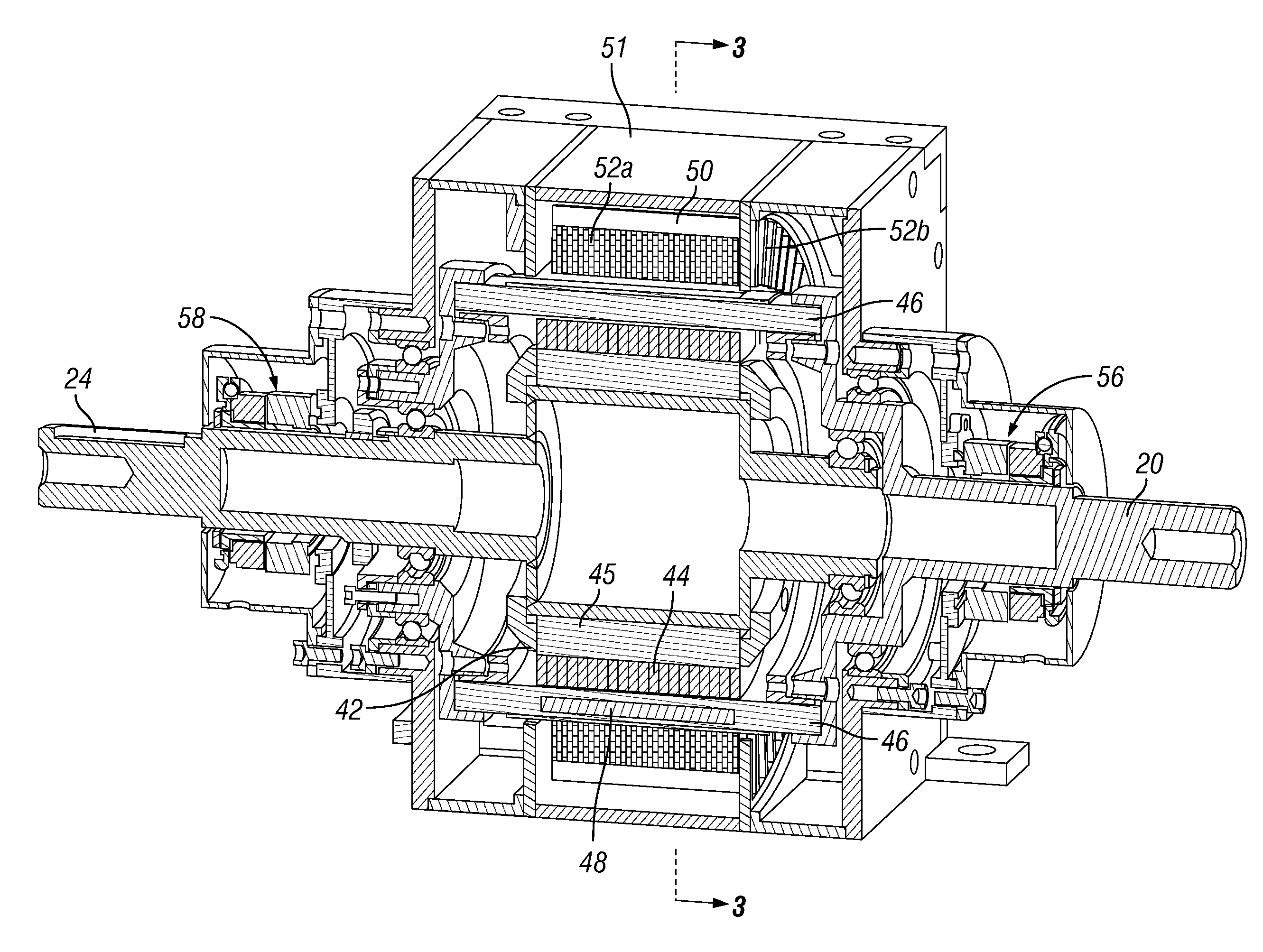
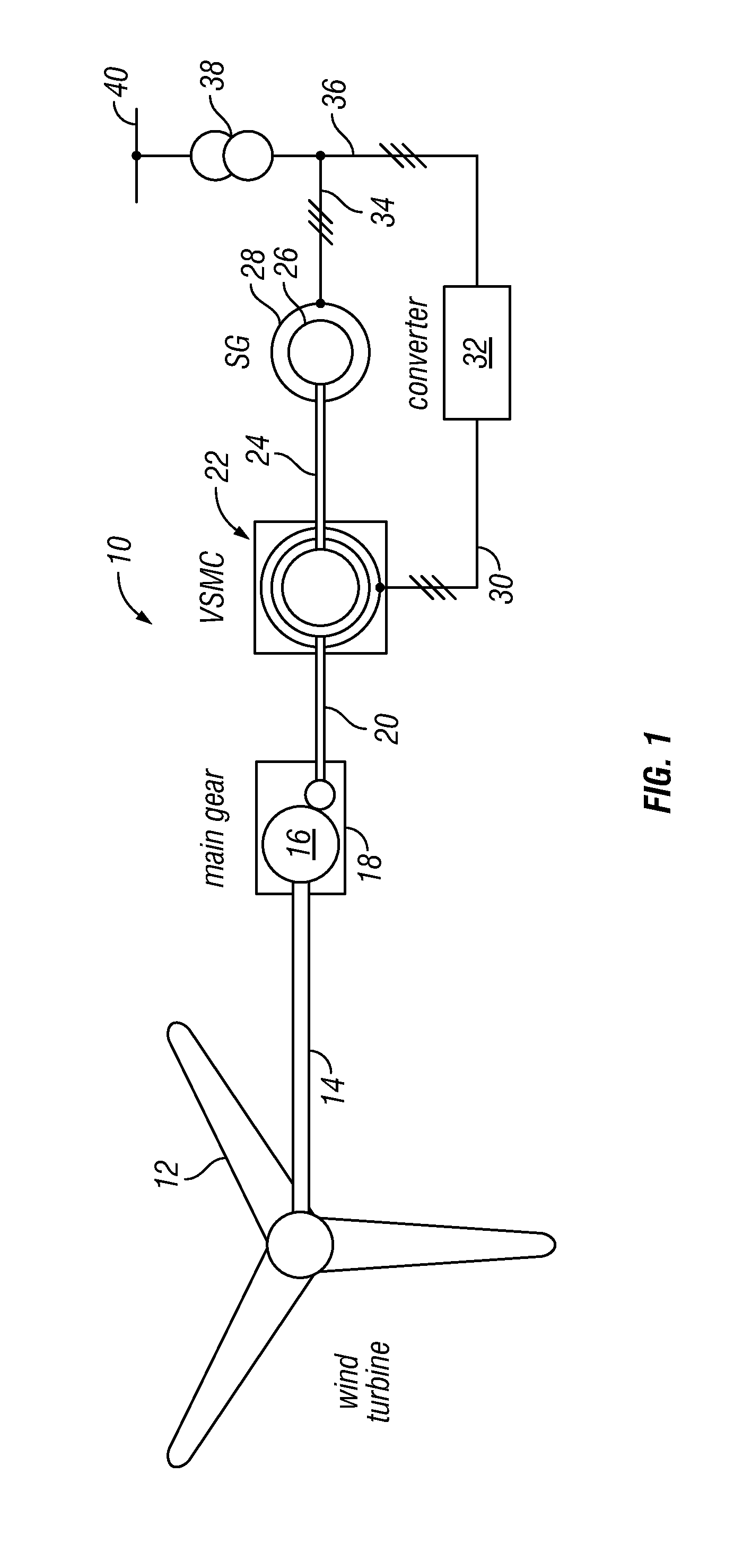
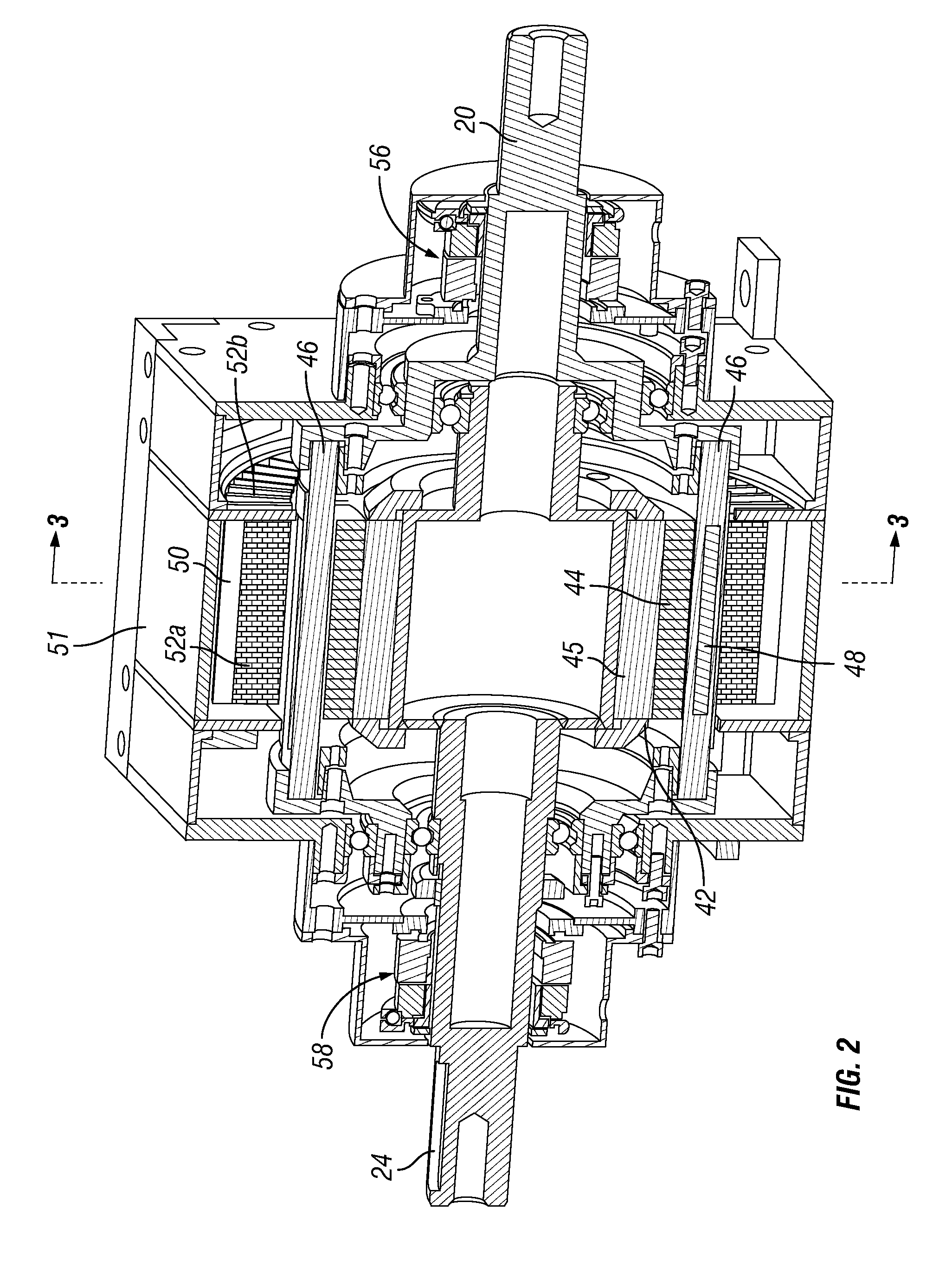
[0018]Referring to FIG. 1, the operational components of a wind turbine 10 include a turbine rotor or sail 12 mounted to one end of an input shaft 14. The other end of the input shaft 14 drives a bull or main gear 16 of a drive train 18. The drive train 18 drives an intermediary shaft 20, which is in turn connected to a variable speed magnetic coupling (VSMC) 22, in accordance with an embodiment of the present invention.

[0019]The VSMC 22 drives an output shaft 24, which turns a rotor 26 of an electrical generator 28. In certain embodiments of the invention, the electrical generator is a multiphase generator. As will be appreciated, however, a direct-current generator or single-phase generator also can be used with appropriate d...


PUM


Abstract

An apparatus includes a first rotor operatively connected to an output shaft and holding a first array of pole pieces; a second rotor operatively connected to an input shaft coaxially with the first rotor and holding a second array of pole pieces; and an array of field windings disposed coaxially with the first and second rotors. The array of field windings being arranged to interact magnetically with a harmonic frequency of the magnetic field of the first or second array of pole pieces in a magnetically geared manner and being selectively energizable to control electromagnetic coupling of the first array of pole pieces with the second array of pole pieces, and thereby to transfer at least one of torque and speed from the input shaft to the output shaft.

Description

FIELD OF THE INVENTION[0001]Embodiments of the invention relate to variable-speed magnetic couplings and control methods and more particularly to drive trains incorporating electromagnetic couplings.BACKGROUND OF THE INVENTION[0002]Renewable forms of energy, such as wind power, have become increasingly desirable sources for meeting present and future electrical power requirements. Wind power typically is harvested through the use of a turbine having a rotor head with blades and a rotatable shaft coupled to the head. The rotatable shaft is connected, either directly or indirectly, to a generator. Key challenges in harvesting wind energy for power generation include reliability and noise quality of the wind source, i.e., accounting for variations in the angular velocity of the rotatable shaft caused by variations in wind speed.[0003]As will be appreciated, generators driven by wind turbines typically include an apparatus for smoothing or filtering variations in the wind input to the t...

Claims


Application Information

Patent Timeline
IPC IPC(8): H02K49/06
CPCF05B2260/404H02K49/106H02K7/1838Y02E10/72
Inventor CURBELO, ALVARO JORGE MARIBRANDHOFF, STEFANCISZAK, ROBERT J.HUBER, JOHANNESHEMMELMANN, JAN E.WASZAK, MICHAL-WOLFGANG
Owner GENERAL ELECTRIC CO
Why Eureka
Try Eureka