

Recording apparatus
a recording apparatus and recording technology, applied in the field of recording apparatuses, can solve the problems of excessive evaporated solvent excessive cooling of high duty regions, etc., and achieve the effect of reducing temperature differences
- Summary
- Abstract
- Description
- Claims
- Application Information
AI Technical Summary
Benefits of technology
Problems solved by technology
Method used
Image

Examples
embodiment 1-a
[0029]First, independent cooling of multiple locations of an intermediate transfer medium in a region in which an intermediate image is formed will be described in detail.
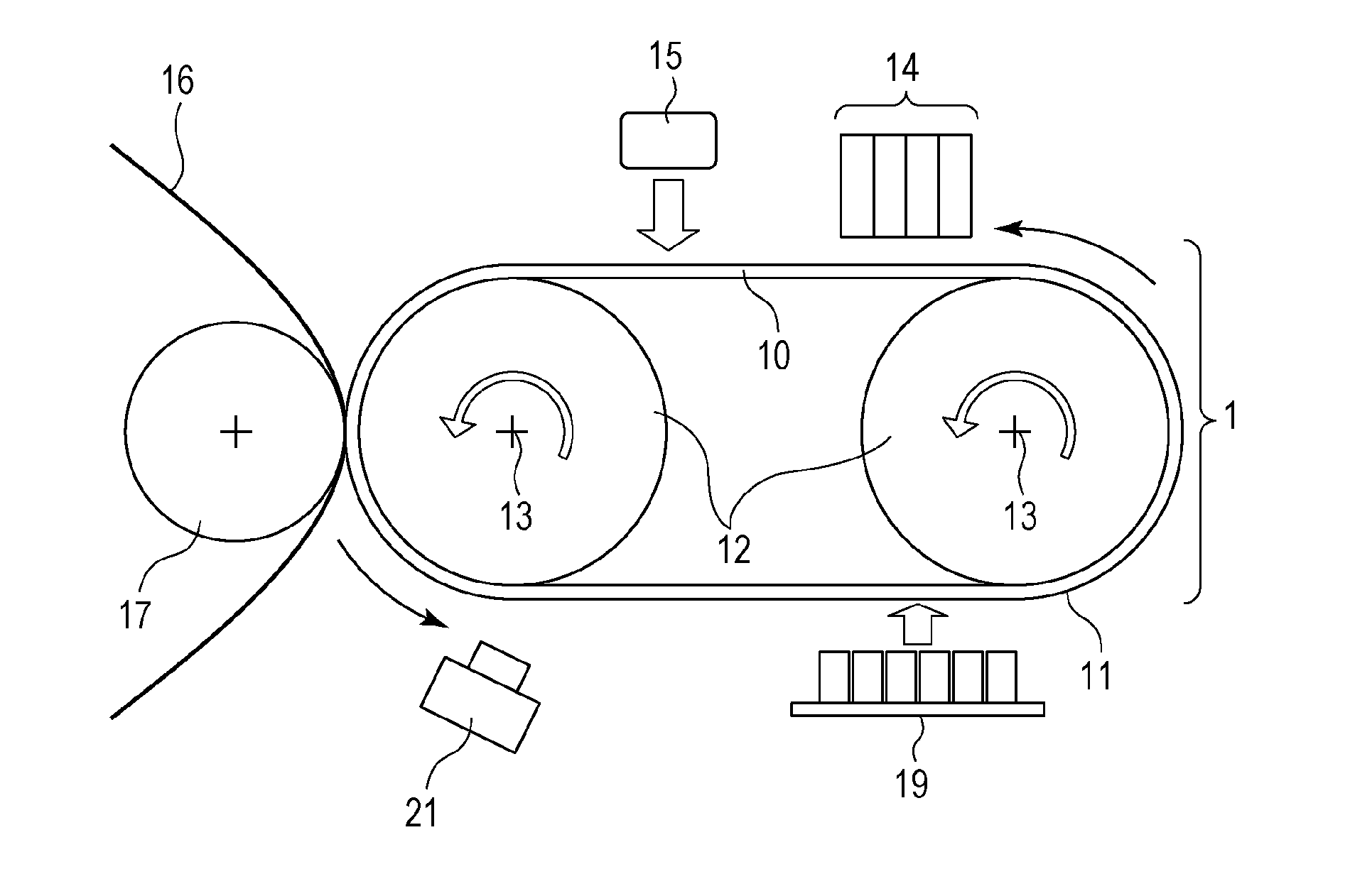
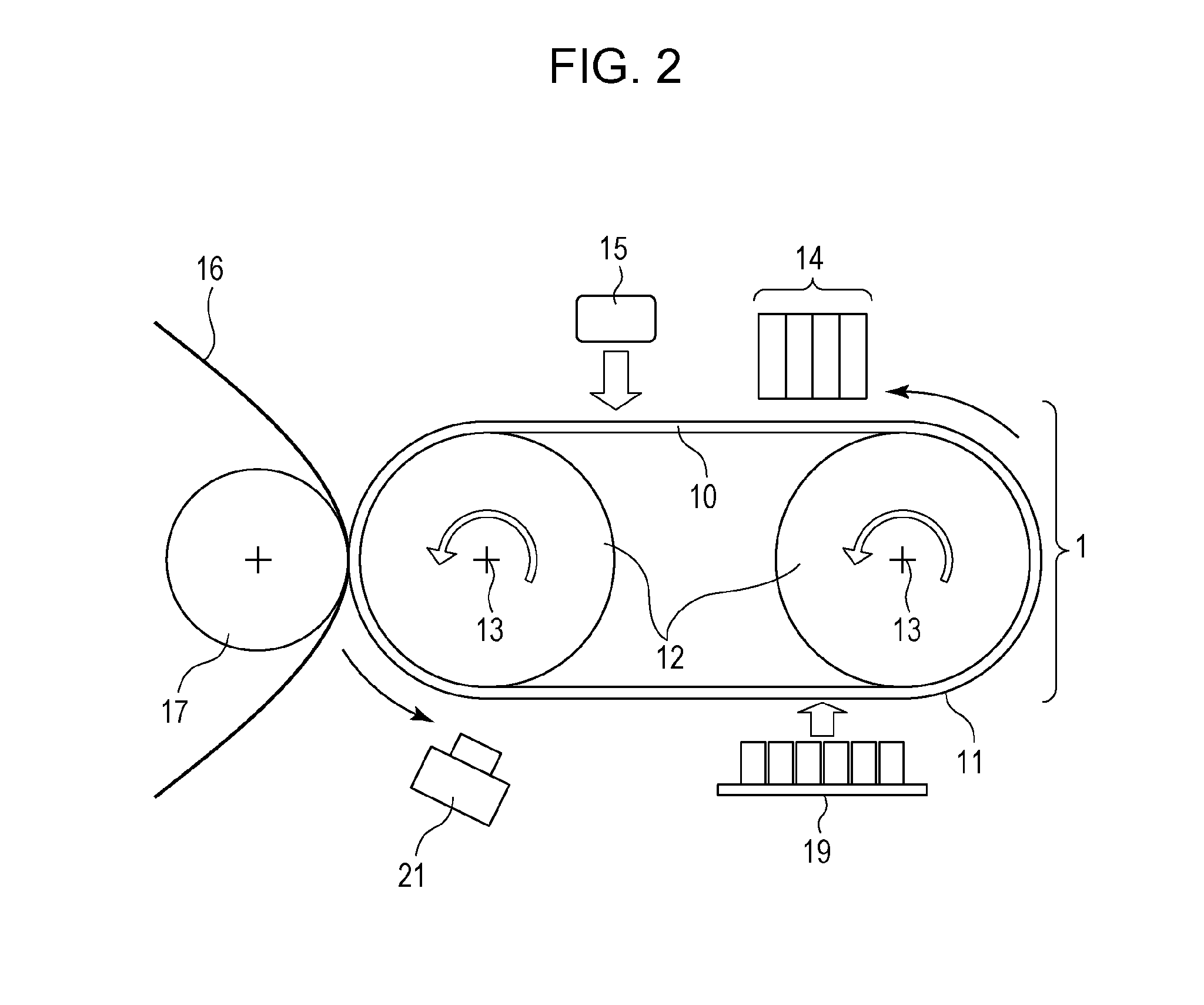
[0030]FIG. 2 illustrates an entire configuration of a recording apparatus of a transfer inkjet recording system according to Embodiment 1. An intermediate transfer medium 1 includes two drum-shaped rotary members 12 and a seamless transfer belt 10; the drum-shaped rotary members 12 rotate in a direction of the arrows about axes 13 and the transfer belt 10 is rotated around the two rotary members 12. The transfer belt 10, made of a metallic material, includes an ink-receiving surface layer 11 on an outer surface thereof.
[0031]A group of units is disposed around the intermediate transfer medium 1 to repeatedly implement recording cycles, each of which consisting of forming, heating, transferring and cooling of an intermediate image. These units are a recording head 14 (for an intermediate image formation process), a ...
embodiment 1-b
[0044]Embodiment 1-b of the present invention will be described. Embodiment 1-b differs from Embodiment 1-a in the heating section 15; other components are the same as those illustrated in FIG. 2. In Embodiment 1-b, not as in the configuration of Embodiment 1-a in which the intermediate image is heated uniformly in the heating process, the image is divided into multiple regions and the heating amount is controlled independently for each of the divided regions.
[0045]The heating amount required to achieve “appropriate ink viscosity” after the heating process differs depending on the average recording duty of each divided region of the image. “Appropriate ink viscosity” herein is the viscosity of ink before the transfer process; at that viscosity, no “insufficient transfer”, such as “image blur” and “image depletion,” occurs in the image transferred to the recording medium.
[0046]FIGS. 8A and 8B are graphic plot of a residual rate (%) of the ink solvent with respect to the heating amoun...
embodiment 2
[0054]Next, independent cooling of regions in each of which an intermediate image is formed on the intermediate transfer medium will be described in detail.
[0055]In FIG. 10A, two types of dot regions represent examples of intermediate images immediately after being formed on the intermediate transfer medium 1. Intermediate images 103 are high duty images with average recording duty of the entire image of 90% (i.e., a first intermediate image) and an intermediate image 102 is a low duty image with average recording duty of 20% (i.e., a second intermediate image). The first intermediate image and the second intermediate image herein are ink images formed at different locations on the transfer medium. Here, the “recording duty” is the ratio of the actual ejection events with respect to the maximum possible ejection events in a single scanning event. For example, if one dot is formed in one ejection event, the ratio of the dot number actually formed with respect to the number of pixels ...
PUM
 Abstract
Description
Claims
Application Information