
Inkjet printing machine

a printing machine and inkjet technology, applied in the field of printing objects, can solve the problems of deteriorating the quality of the printing on the objects, increasing and inability to achieve in an automated manner, and achieving the effect of reducing the difficulty of manual printing

Inactive Publication Date: 2012-04-26
MACHINES DUBUIT
View PDF49 Cites 29 Cited by
  • Summary
  • Abstract
  • Description
  • Claims
  • Application Information

AI Technical Summary

Benefits of technology

[0010]It is an object of the present invention to provide a printing machine making it possible to achieve great precision in the printing of objects while being easy to implement and making it possible to increase the printing rhythms of the objects.
[0012]Since the printing station comprises a single mandrel and only prints the objects supported by said mandrel, it is possible to achieve great precision in the positioning of the mandrel relative to the printing units and to perfectly know the rotational speed profile of the mandrel and obtain a constant speed of rotation. Thus, it is not necessary to perform a new adjustment for each object to be printed, the positioning of the objects being strictly identical from one object to another supported by that same single mandrel corresponding to the printing station. High-quality printing is thus obtained and it is possible to increase the printing rhythms.
[0015]each printing unit can be moved in a substantially radial direction relative to the axis of rotation of the mandrel so as to make it possible to move the printing unit away from or closer to said axis of rotation as a function of the diameter of the object to be printed;
[0022]the mandrel is translationally mobile along its axis so as to make it possible to expose several areas of the maintained object to the inkjet from the printing unit;

Problems solved by technology

However, since it is not possible to position each mandrel precisely relative to the printing units due to the mechanical and machining allowances, the inkjets do not converge on the surface of the objects, which results in a deteriorated quality of the printing on the objects.
This problem is also increased if the rotational speed profiles vary from one mandrel to the other, the printing units being controlled to project the ink as a function of said speeds of rotation.
Thus, to have satisfactory printing, it would be necessary to refine the adjustment of the position of each mandrel and its speed of rotation so that they are strictly identical from one mandrel to another, which is impossible to do in an automated manner and is completely incompatible with large-scale production rhythms.
Furthermore, such a printer does not make it possible to easily increase the number of printing units around a mandrel, to increase the printing rhythms.
In fact, it is necessary to provide a space to allow the mandrel to move between its printing position and its transfer position, which limits the choices in the positioning of the printing units, the units having to be distributed while covering at most an angle of 180°, i.e. over a semi-circle, to allow the mandrel to go from its transfer position to its printing position.

Method used


Image

  • Inkjet printing machine
  • Inkjet printing machine
  • Inkjet printing machine

Examples


Embodiment Construction

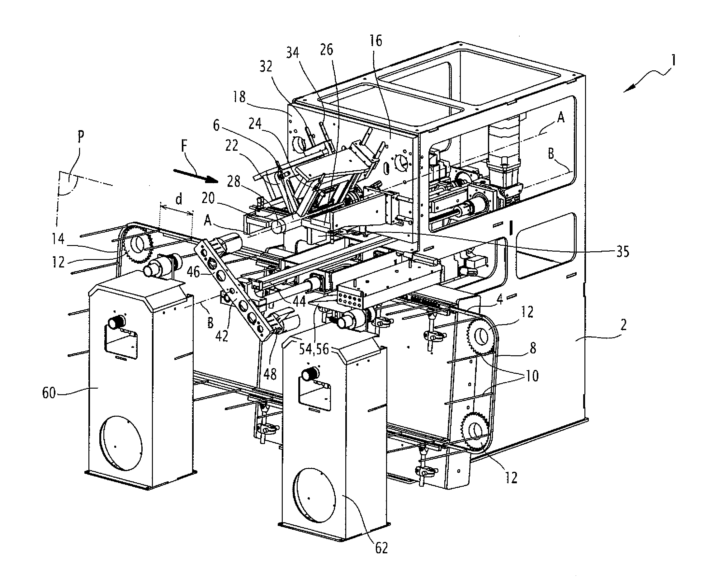
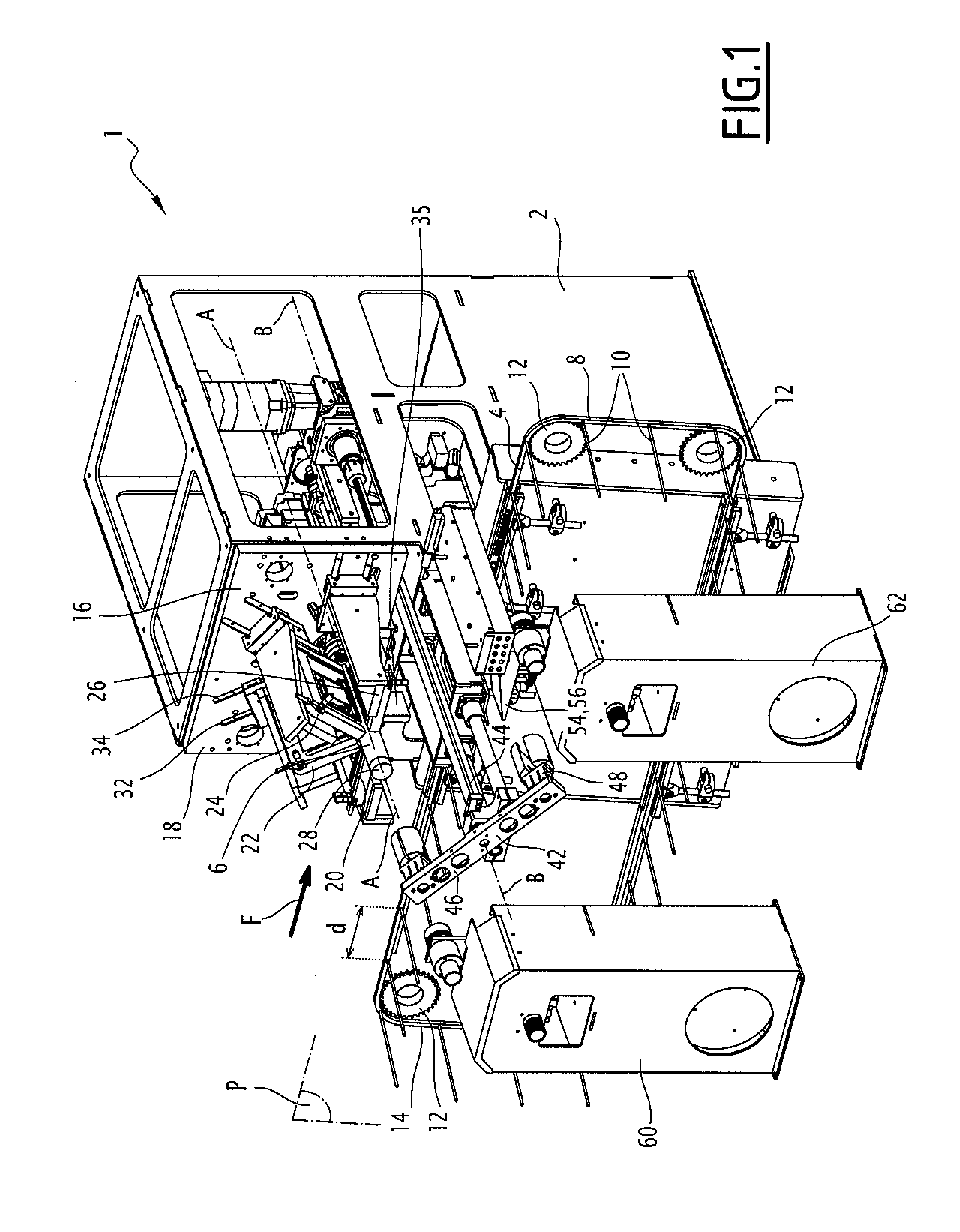
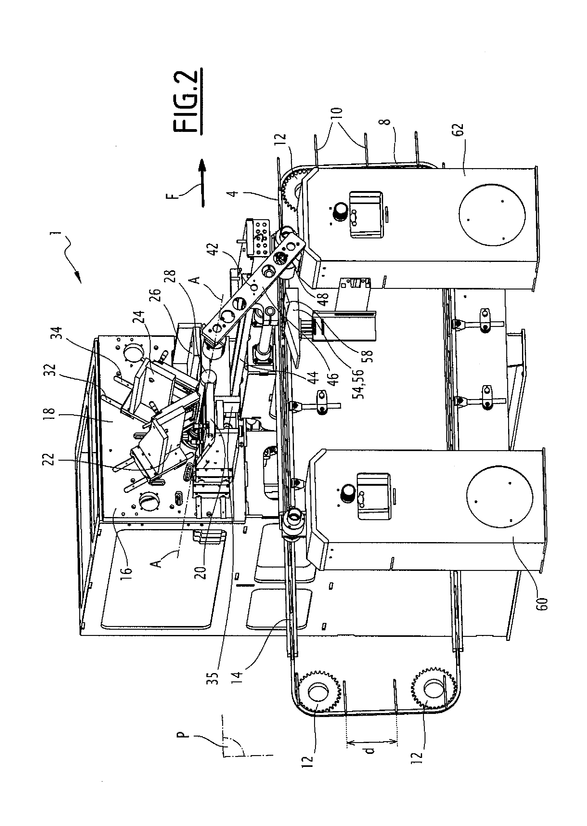
[0038]The printing machine 1 according to the invention is shown in FIGS. 1 and 2. It comprises a frame 2 supporting transport means 4 for objects 6 to be printed. The objects 6 to be printed substantially have shapes of revolution, such as substantially cylindrical tubes or containers.

[0039]The transport means 4 are formed by an endless conveyor 8, supporting a plurality of fingers 10 for receiving an object to be printed, separated from one another by a distance d defining the pitch of the transport means. The conveyor 8 is for example formed by a belt closed on itself, such as a transport chain, arranged around driving means 12, such as toothed wheels, arranged so that the conveyor has a substantially rectangular shape. The driving means 12 are rotatably mounted on the frame 2 and at least one of the driving means 12 is rotated by a motor so as to make the belt 8 circulate in a circulation plane P, in which the entire conveyor 8 extends, on the driving means 12. The branch 14 of ...


PUM


Abstract

The printing machine (1) according to the invention includes:a transporter (4) for transporting objects (6) to be printed,a printing station (16) including at least four printing units (20, 22, 24, 26) arranged to project ink on the objects (6) to be printed,a transfer device (42) for transferring an object (6) to be printed from the transporter (4) to the printing station (16) and from the printing station (16) to the transporter (4).The printing station (16) includes a single mandrel (28) corresponding to the maintenance of an object (6) to be printed, the corresponding mandrel (28) being rotatably movable around its axis (A-A) so that the printing units (20, 22, 24, 26) project ink onto the object (6) maintained by the corresponding mandrel (28), the printing station (16) being arranged to print only the objects (6) maintained by the corresponding mandrel (28).

Description

[0001]This claims the benefit of French Patent Application FR 10 587 17, filed Oct. 25, 2010 and hereby incorporated by reference herein.BACKGROUND[0002]The present invention relates to a machine for printing objects substantially having shapes of revolution of the type comprising:[0003]means for transporting objects to be printed between at least one station for loading objects on said transport means and a station for unloading said objects from said transport means,[0004]at least one printing station arranged between the loading station and the unloading station, said printing station comprising at least four printing units arranged to project ink on the objects to be printed so as to print said objects, each printing unit projecting ink of a different color so as to make up a four-color process,[0005]means for transferring an object to be printed from the transport means to the printing station and from the printing station to the transport means.[0006]Document EP-1 918 100 desc...

Claims


Application Information

Patent Timeline
IPC IPC(8): B41J2/01
CPCB41J3/543B41J3/4073B41J3/40733B41J3/283B41J3/286
Inventor DUBUIT, JEAN-LOUISDUMENIL, FRANCOISGAVET, FABIEN
Owner MACHINES DUBUIT
Learn More