Unlock instant, AI-driven research and patent intelligence for your innovation.

Scanning projective lensless microscope system

a projective, lensless technology, applied in the field of projective scanning projective lensless microscopy, can solve the problems of difficult miniaturization, high cost, and bulky optics of conventional optical microscopes, and neither can work well with confluent cell cultures or any sampl

Active Publication Date: 2012-04-26
CALIFORNIA INST OF TECH
View PDF23 Cites 83 Cited by
  • Summary
  • Abstract
  • Description
  • Claims
  • Application Information

AI Technical Summary

Benefits of technology

[0037]Embodiments of the invention provide one or more technical advantages. In an SPLM system of embodiments, the scanning illumination source is located at a larger distance from the sensing surface as compared to the distance between the object and the sensing surface. Thus, small translations of the light element correspond to larger translations of the projections on the sensing surface. With this geometry, the scanning illumination source can easily and accurately control and maintain sub-pixel shifts of the projections. This can provide an advantage over other systems, such as prior microscanning systems, that used actuators and controller to control sub-pixel movements of the object or a platform holding the object. Another advantage of embodiments is that this method may provide an autonomous, cost effective, high quality microscopic solution for high resolution imaging of confluent samples and other samples in which objects (e.g., cells) are contiguously connected over a sizable length.

Problems solved by technology

Conventional optical microscopes have bulky optics, and have proven to be expensive and difficult to miniaturize.
However, neither can work well with confluent cell cultures or any sample in which cells are contiguously connected over a sizable length scale.
Adherent, confluent, or contiguously arranged specimens are usually incompatible with imaging in a fluidic mode.
In addition, the field of view may be limited by the geometry of the fluid channel.
However, such approaches appear to have not been applied to targets that occupy more than 0.1 mm2 in total contiguous area coverage with submicron resolution, as found in Repetto, Madanyali, Xu, Garcia-Sucerquia, and also in Biener, G., et al., “Combined reflection and transmission microscope for telemedicine applications in field settings,” Lab Chip, Vol. 11, pp.
The reason for this limitation is well-known: the loss of phase information during the intensity recording process.
The generated images based on these mitigating methods have artifacts that may arise from interference, and are identifiably different and of lower quality than images acquired with conventional microscopes due to coherence based noise sources.

Method used


Image

  • Scanning projective lensless microscope system
  • Scanning projective lensless microscope system
  • Scanning projective lensless microscope system

Examples


Embodiment Construction

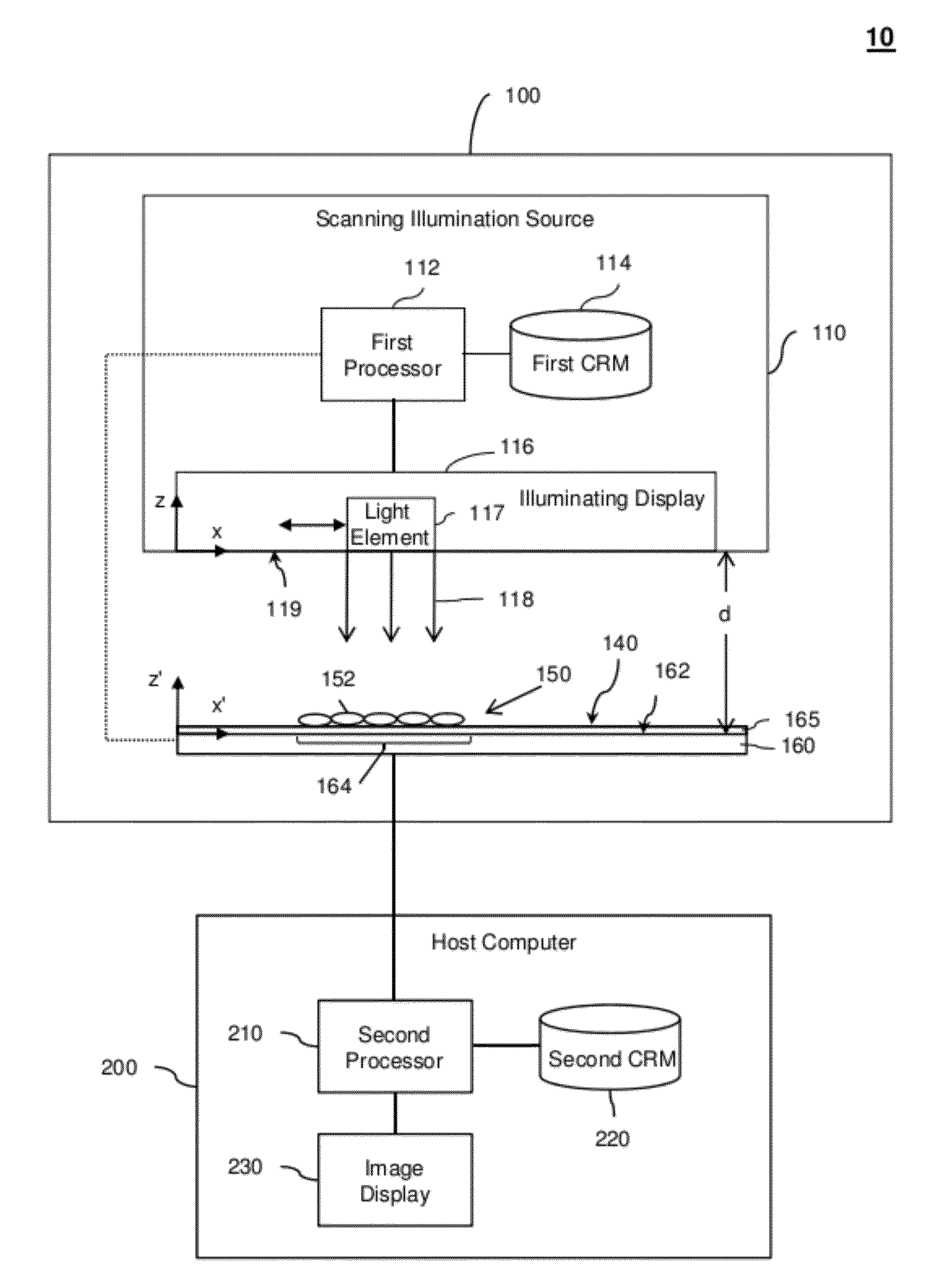
[0036]Embodiments of the present invention will be described below with reference to the accompanying drawings. Some embodiments include an SPLM device having a specimen surface with an object being imaged, a scanning illumination source (e.g. a smartphone), a light detector (e.g., CMOS imaging sensor) having a sensing surface, a thin transparent layer between the sensing surface and the specimen surface, and a processor. During a scanning cycle, the scanning illumination source scans (sweeps) or otherwise translates a light element (e.g., one or more pixels of an LCD) to different scanning locations to illuminate the object from different illumination angles. For example, different sets of pixels on an LCD may be sequentially illuminated. The illumination from the light element generates sub-pixel shifted projections of the object on the sensing surface of the light detector. The light detector records a sequence of sub-pixel shifted LR projection images associated with the locatio...


PUM


Abstract

A scanning projective lensless microscope device comprises a specimen surface, a scanning illumination source with a light element, a light detector outside the specimen surface, and a processor. The scanning illumination source scans the light element to a plurality of scanning locations to provide illumination to an object on the specimen surface. The light detector samples a sequence of sub-pixel shifted projection object images corresponding to the plurality of scanning locations. The processor constructs a high resolution image of the object based on the sequence of sub-pixel shifted projection images and a motion vector of the projections at a plane of interest.

Description

CROSS-REFERENCES TO RELATED APPLICATIONS[0001]This is a non-provisional application of, and claims priority to, U.S. Provisional Patent Application No. 61 / 406,916 entitled “Scanning Projective Microscopy System for 2D and 3D Imaging” filed on Oct. 26, 2010 and U.S. Provisional Patent Application No. 61 / 482,531 entitled “ePetri: An On-Chip Cell Imaging Platform based on Sub-Pixel Perspective Sweeping Microscopy” filed on May 4, 2011. Those provisional applications are hereby incorporated by reference in their entirety for all purposes.[0002]This non-provisional application is related to the following co-pending and commonly-assigned patent application, which is hereby incorporated by reference in its entirety for all purposes:[0003]U.S. patent application Ser. No. 12 / 398,050 entitled “Optofluidic Microscope Device with Photosensor Array” filed on Mar. 4, 2009.[0004]U.S. patent application Ser. No. 13 / 069,651 entitled “Super Resolution Optofluidic Microscopes for 2D and 3D Imaging” fi...

Claims


Application Information

Patent Timeline
IPC IPC(8): H04N7/18
CPCG02B21/06H04N7/183G02B21/367G02B21/0008G03H2001/0447
Inventor ZHENG, GUOANYANG, SAMUELLEE, SEUNG AHYANG, CHANGHUEI
Owner CALIFORNIA INST OF TECH
Features
  • R&D
  • Intellectual Property
  • Life Sciences
  • Materials
  • Tech Scout
  • Unparalleled Data Quality
  • Higher Quality Content
  • 60% Fewer Hallucinations
Learn More