Pll circuit, and radio communication device equipped therewith

a radio communication device and circuit technology, applied in the direction of radio transmission, electrical equipment, automatic control, etc., can solve the problem of reducing the accuracy of convergence, and achieve the effect of increasing the convergence time and reducing the time taken in estimation processing

Inactive Publication Date: 2012-04-26
SEMICON COMPONENTS IND LLC +1
View PDF4 Cites 31 Cited by
  • Summary
  • Abstract
  • Description
  • Claims
  • Application Information

AI Technical Summary

Benefits of technology

[0009]When the mode is switched in the ADPLL circuit employing the above method, the DCO gain in the mode is estimated, and a parameter for normalizing the estimated DCO gain is set. Thereafter, the convergence frequency in that mode is searched. The time taken in the estimation processing of the DCO gain is a cause of increasing the convergence time.
[0010]Under such circumstances, the inventors of the present application has found a method for reducing the time taken in the estimation processing of the DCO gain executed during switching of the mode, as compared with the currently available method.

Problems solved by technology

On the other hand, when the value of the loop gain is large, it takes a shorter convergence time to attain the target frequency, but the frequency change becomes rough, which reduces the accuracy of convergence.

Method used


Image

  • Pll circuit, and radio communication device equipped therewith
  • Pll circuit, and radio communication device equipped therewith
  • Pll circuit, and radio communication device equipped therewith

Examples


Embodiment Construction

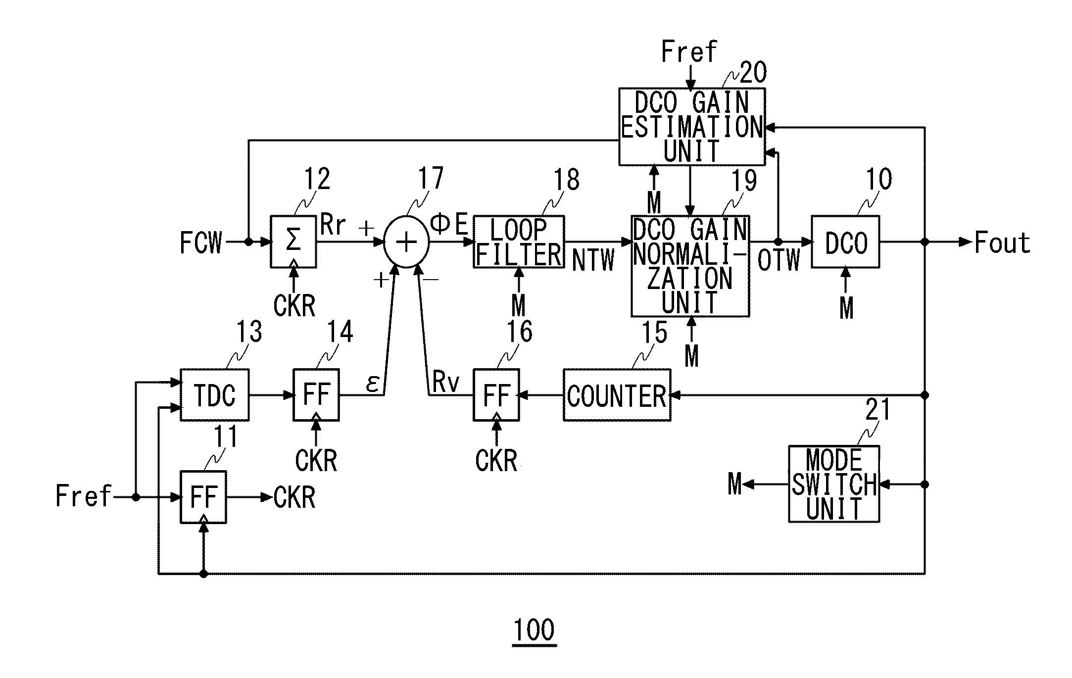
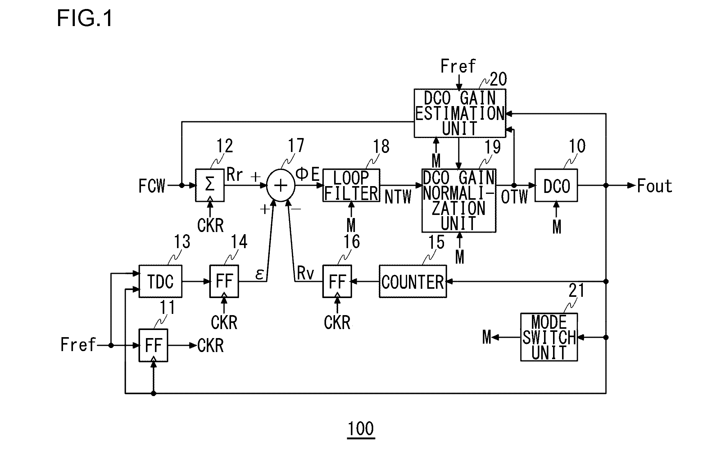
[0023]FIG. 1 is a figure illustrating a configuration of an ADPLL circuit 100 according to an embodiment of the present invention. The ADPLL circuit 100 includes a digitally controlled oscillator 10, a retiming clock generation unit 11, an accumulator 12, a time / digital converter (TDC) 13, a first flip-flop circuit 14, a counter 15, a second flip-flop circuit 16, a phase detector 17, a loop filter 18, a DCO gain normalization unit 19, a DCO gain estimation unit 20, and a mode switch unit 21.

[0024]The digitally controlled oscillator 10 oscillates at a frequency according to a set digital value. The retiming clock generation unit 11 generates a retiming clock signal CKR by retiming a reference frequency signal Fref on the basis of an output signal Fout given by the digitally controlled oscillator 10.

[0025]The reference frequency signal Fref is generated by, e.g., a crystal oscillator, not shown. In the present embodiment, an oscillator oscillating at a frequency of about 20 to 40 MHz ...


PUM


Abstract

In an ADPLL circuit, on the basis of a gain of a digitally controlled oscillator estimated when a loop gain of a certain value is set in the loop filter and on the basis of a device parameter of the digitally controlled oscillator, the DCO gain estimation unit estimates a gain of the digitally controlled oscillator when a loop gain of another value is set in the loop filter.

Description

RELATED APPLICATIONS[0001]This application is the U.S. National Phase under 35 U.S.C. §371 of International Application No. PCT / JP2010 / 004255, filed on Jun. 28, 2010, which in turn claims the benefit of Japanese Application No. 2009-157749, filed on Jul. 2, 2009, the disclosures of which Applications are incorporated by reference herein.FIELD OF THE INVENTION[0002]The present invention relates to a PLL circuit using a Digitally Controlled Oscillator (DCO) and a radio communication apparatus equipped with the PLL circuit.DESCRIPTION OF THE RELATED ART[0003]In recent years, an All Digitally Phase Locked Loop (ADPLL) circuit in which most of constituent elements of the PLL circuit are achieved with digitally circuits has been developed. The ADPLL circuit is different from a conventional analog PLL circuit in that the ADPLL circuit does not require any charge pump circuit or any analog LPF, and therefore the size of the PLL circuit can be reduced. In addition, the ADPLL circuit is advan...

Claims


Application Information

Patent Timeline
Patent Type & Authority Applications(United States)
IPC IPC(8): H04B1/06H04B7/00H03L7/08
CPCH03L7/099H03L2207/50H03L7/1075H03L7/101H03L7/06H03L7/107
Inventor DAN, TORUTANABE, TOMOYUKIKOBAYASHI, HARUO
Owner SEMICON COMPONENTS IND LLC
Why Eureka
Try Eureka