Patterning device for generating a pattern in and/or on a layer

a technology of pattern generation and layer, applied in the field of pattern generation devices, can solve the problem of too long pattern generation time and achieve the effect of convenient user interfa

Inactive Publication Date: 2012-05-03
KONINKLIJKE PHILIPS ELECTRONICS NV
View PDF2 Cites 14 Cited by
  • Summary
  • Abstract
  • Description
  • Claims
  • Application Information

AI Technical Summary

Benefits of technology

[0006]It is an object of the invention to provide a patterning device in which the patterning time, being the time to generate a specific pattern, is reduced.

Problems solved by technology

A disadvantage of known patterning devices is that the generation of a pattern takes too long.

Method used


Image

  • Patterning device for generating a pattern in and/or on a layer
  • Patterning device for generating a pattern in and/or on a layer
  • Patterning device for generating a pattern in and/or on a layer

Examples


Embodiment Construction

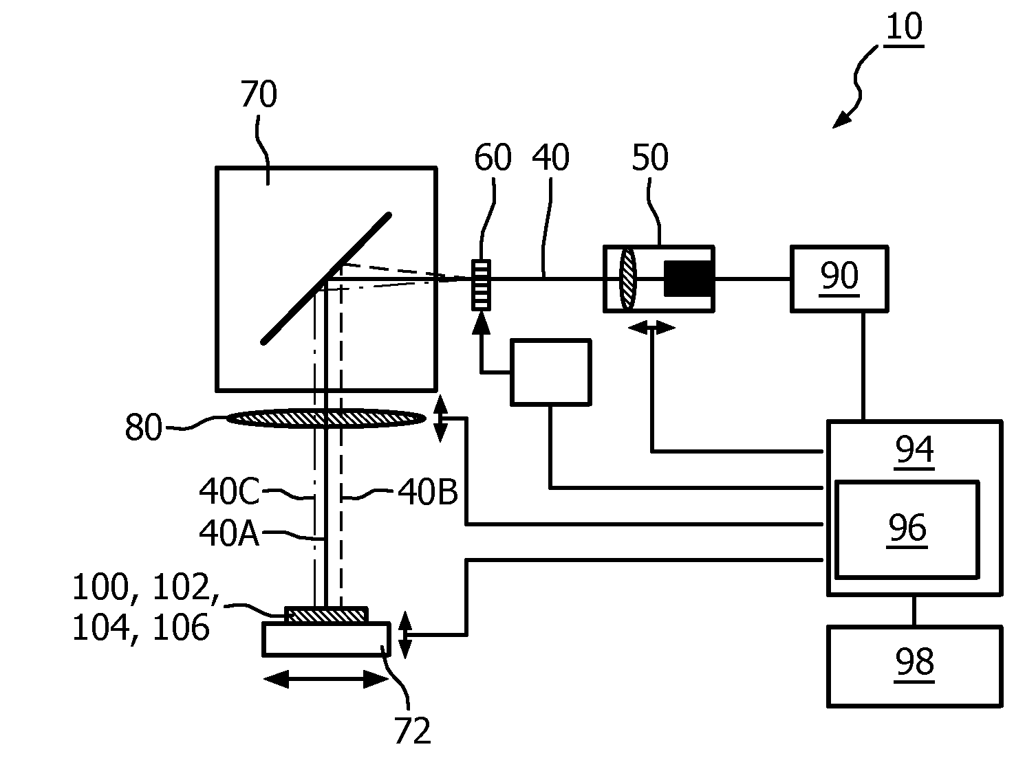
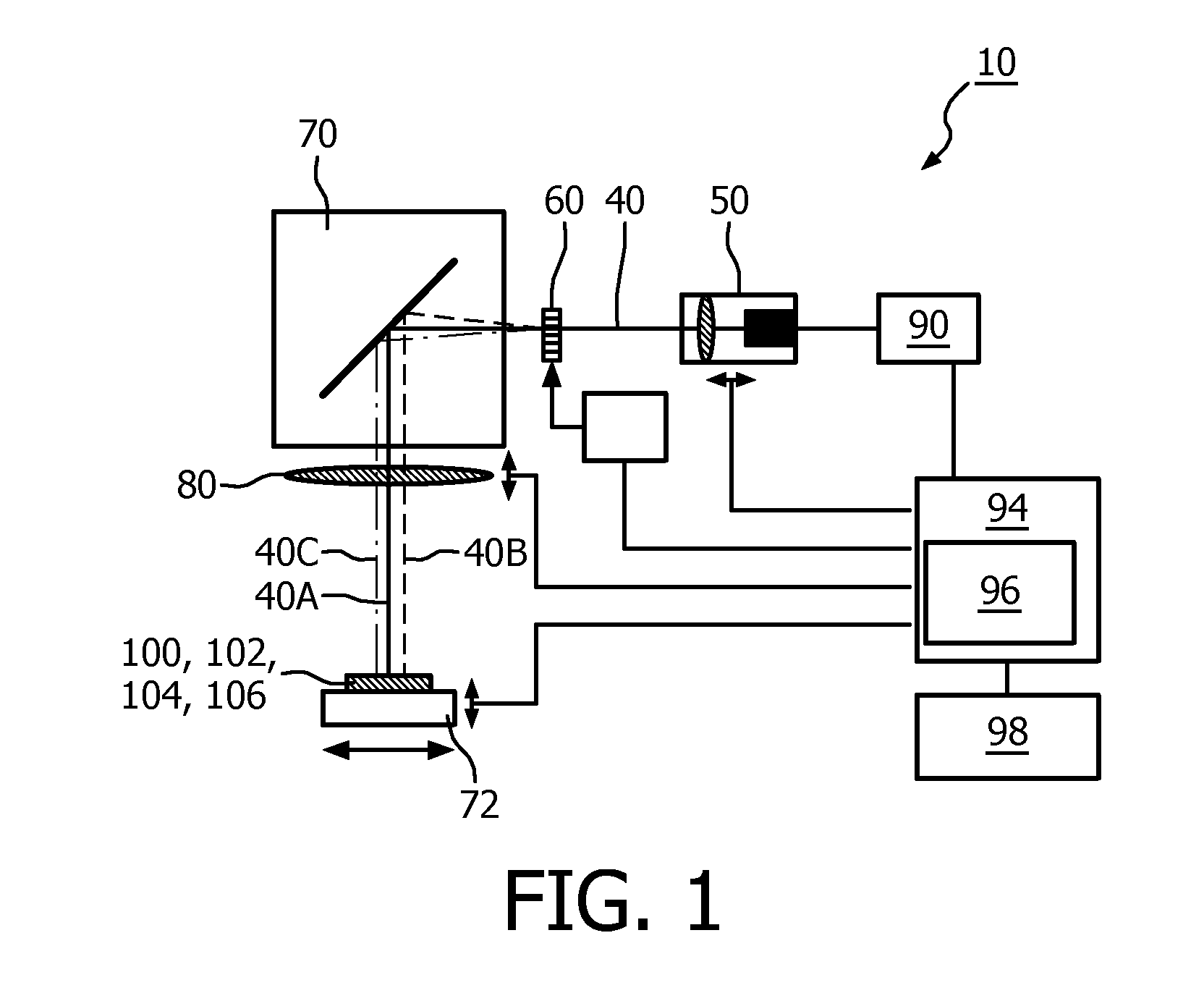
[0042]FIG. 1 shows a schematic cross-sectional view of a patterning device 10 according to the invention for generating a pattern 20, 22, 24 (see FIGS. 4 and 5) in and / or on a layer 32, 34 (see FIGS. 4 and 6). The patterning device 10 comprises a light source 50 for generating a condensed light beam 40 and comprises scanning means 70, for example, a movable mirror 70 or a movable exposure chuck 72 on which a substrate comprising the layer 32, 34 may be located. The patterning device 10 further comprises a diffractive optical element 60 for splitting the condensed light beam 40 into a plurality of condensed sub-beams 40A, 40B, 40C. Via the diffractive optical element 60, a single condensed light beam 40 is split into a plurality of condensed sub-beams 40A, 40B, 40C such that the plurality of condensed sub-beams may be used for generating the pattern 20, 22, 24. As such, especially when having to generate a pattern 20, 22, 24 comprising a relatively large area of substantially equal g...


PUM

PropertyMeasurementUnit
wavelengthaaaaaaaaaa
currentaaaaaaaaaa

Abstract

The invention relates to a patterning device (10, 12) for generating a pattern (20, 22, 24) in and / or on a layer (32, 34) via a condensed light beam (40). The patterning device comprises a light source (50) for generating the condensed light beam (40), a diffractive optical element (60) for splitting the condensed light beam (40) into a plurality of condensed sub-beams (40A, 40B, 40C) and positioning means (70) for positioning the layer relative to the plurality of condensed sub-beams for generating the pattern. The condensed sub-beams are configured for generating the pattern in and / or on the layer. At least two sub-beams of the plurality of condensed sub-beams comprise substantially equal intensity. An effect of the patterning device according to the invention is that a single condensed light beam is split into a plurality of condensed sub-beams to generate a multi-spot patterning for patterning relatively large areas using the plurality of condensed sub-beams. As such, the patterning time for filling that area in the pattern and for generating the pattern in and / or on the layer is considerably reduced.

Description

FIELD OF THE INVENTION[0001]The invention relates to a patterning device for generating a pattern in and / or on a layer.BACKGROUND OF THE INVENTION[0002]Patterning devices for generating a pattern in and / or on a layer of a substrate using a condensed light beam are known in the art. These known patterning devices use, for example, laser light sources to generate a condensed light beam. The condensed light beam has sufficient energy density to locally, for example, damage the layer to make the pattern visible. As such the patterning device comprises means to move the condensed light beam across the surface of the substrate to generate or write the pattern.[0003]Organic light emitting diode devices (further also referred to as OLED devices) are in many ways considered as the future in various lighting applications. They may, for instance, be used to create ambient lighting. OLED devices typically comprise a cathode, an anode, an emissive organic layer. These parts are typically stacked...

Claims


Application Information

Patent Timeline
Patent Type & Authority Applications(United States)
IPC IPC(8): B01J19/12
CPCB23K26/0656B23K26/0676H01L51/0017G03F7/70383B23K26/0853B23K26/066H10K71/231
Inventor VERSCHUREN, COEN ADRIANUS
Owner KONINKLIJKE PHILIPS ELECTRONICS NV
Why Eureka
Try Eureka