Spread spectrum clock generating circuit

a clock generator and spectrum technology, applied in the direction of electrical equipment, pulse automatic control, etc., can solve problems such as system failure, and achieve the effect of reducing electro magnetic interference (emi)

Active Publication Date: 2012-05-03
ELECTRONICS & TELECOMM RES INST
View PDF10 Cites 16 Cited by
  • Summary
  • Abstract
  • Description
  • Claims
  • Application Information

AI Technical Summary

Benefits of technology

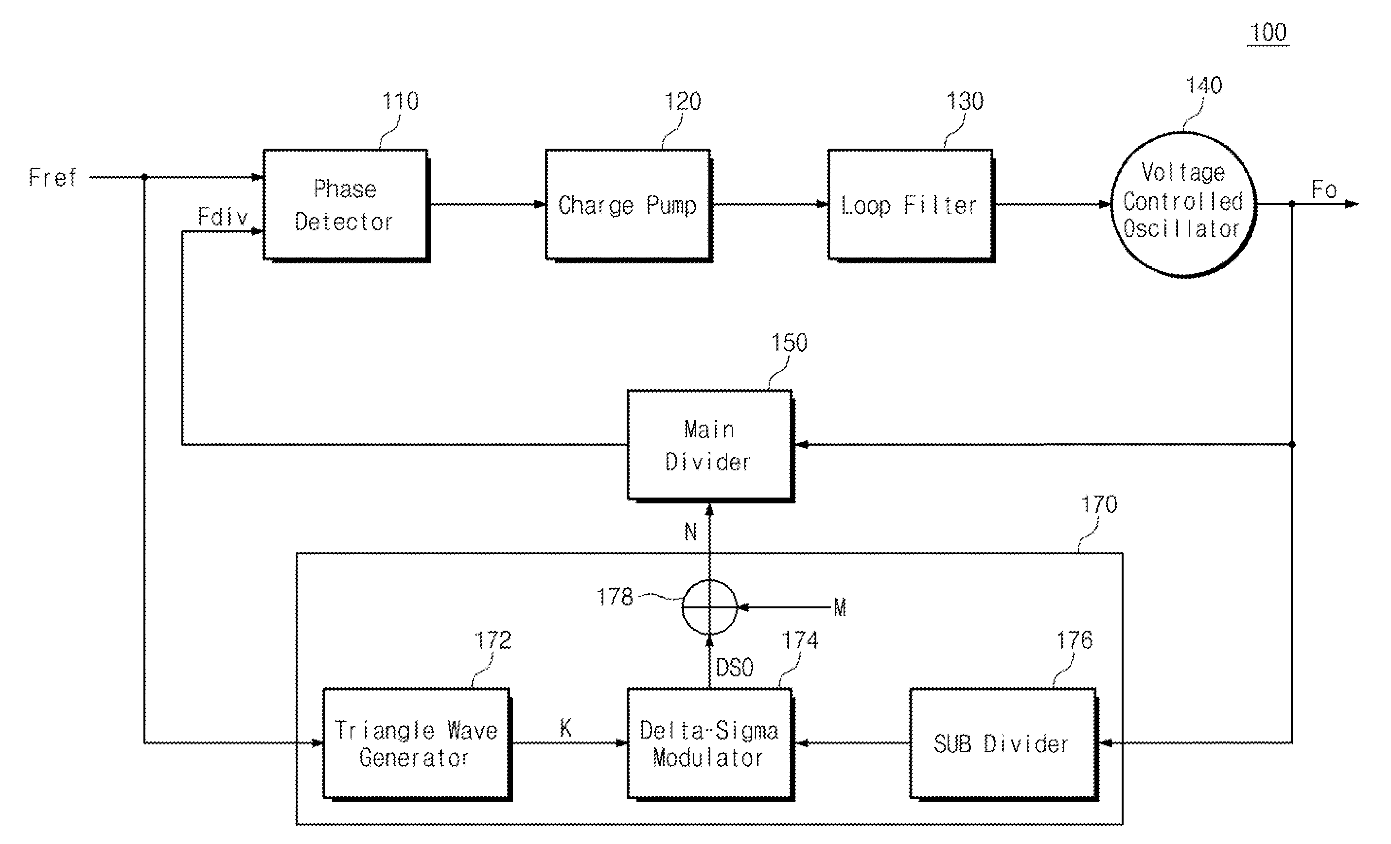
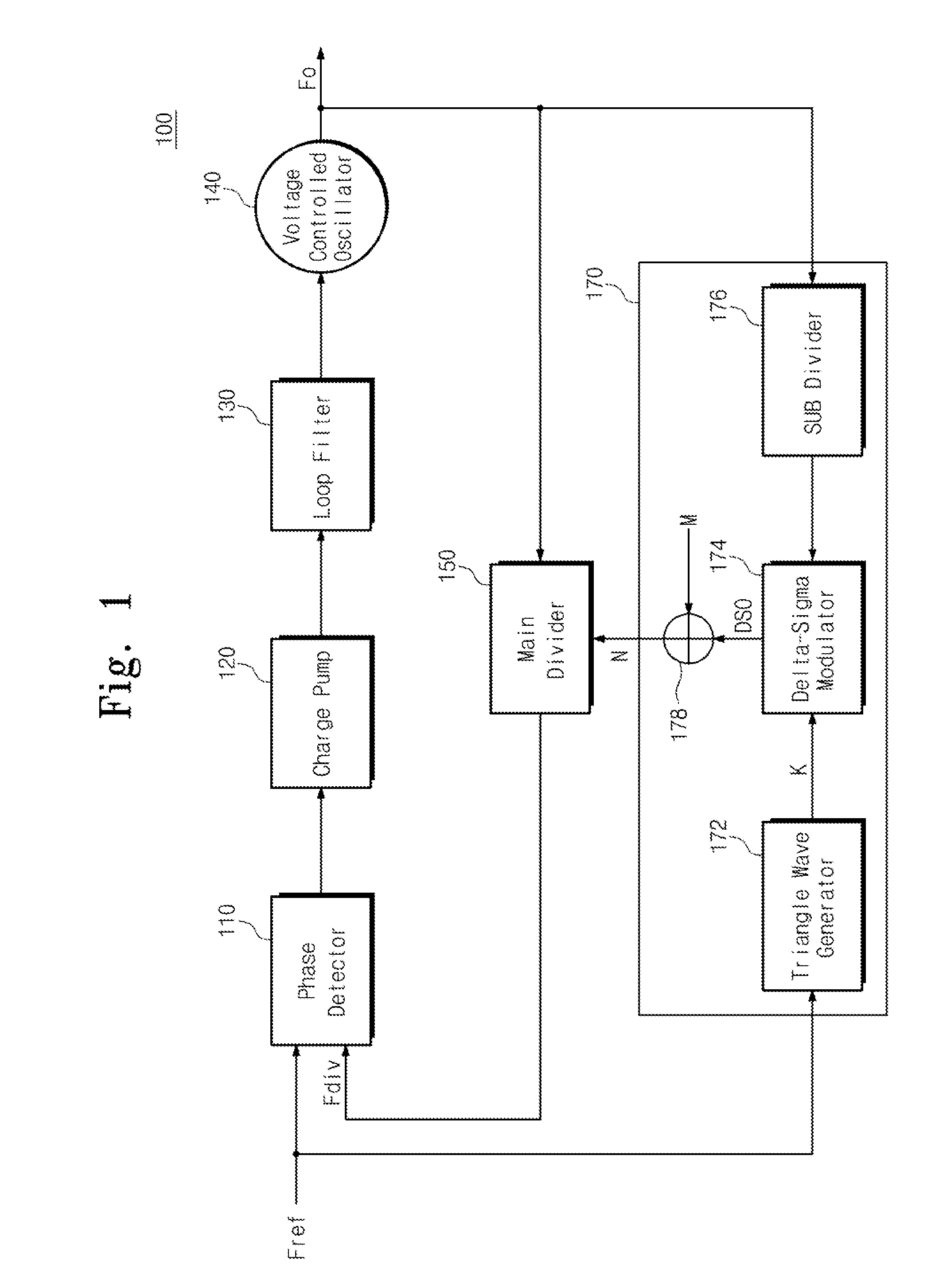
[0005]The present invention provides a spread spectrum clock generating circuit controlling a dividing ratio to reduce Electro Magnetic Interference (EMI) occurring due to an oscillation frequency.

Problems solved by technology

If a frequency of a clock signal becomes higher, Electro Magnetic Interference (EMI) may occur to cause system failure.

Method used


Image

  • Spread spectrum clock generating circuit
  • Spread spectrum clock generating circuit
  • Spread spectrum clock generating circuit

Examples


Embodiment Construction

[0024]Preferred embodiments of the present invention will be described below in more detail with reference to the accompanying drawings. The present invention may, however, be embodied in different forms and should not be constructed as limited to the embodiments set forth herein. Rather, these embodiments are provided so that this disclosure will be thorough and complete, and will fully convey the scope of the present invention to those skilled in the art. Like reference numerals refer to like elements throughout.

[0025]In the drawings, the dimensions of layers and regions are exaggerated for clarity of illustration. It will also be understood that when a layer (or film) is referred to as being ‘on’ another layer or substrate, it can be directly on the other layer or substrate, or intervening layers may also be present. Further, it will be understood that when a layer is referred to as being ‘under’ another layer, it can be directly under, and one or more intervening layers may also...


PUM


Abstract

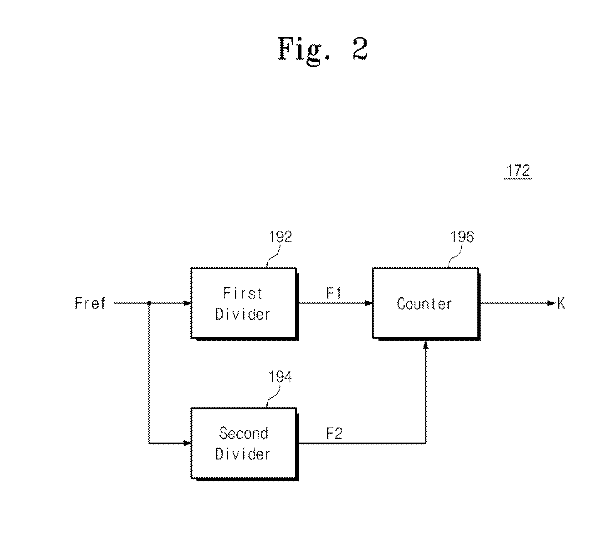
Provided is a spread spectrum clock generating circuit. The spread spectrum clock generating circuit includes: a phase detector receiving a reference frequency signal from the external and detecting a phase difference between the reference frequency signal and a frequency-divided signal; a voltage controlled oscillator outputting an oscillation signal corresponding to a detection result of the phase detector; a main divider generating the frequency-divided signal by dividing a frequency of the oscillation signal by a main dividing ratio; and a dividing ratio controller generating a variable count value, generating a sub dividing ratio by performing delta-sigma modulation according to the count value, and adjusting the main dividing ratio according to the sub dividing ratio.

Description

CROSS-REFERENCE TO RELATED APPLICATIONS[0001]This U.S. non-provisional patent application claims priority under 35 U.S.C. §119 of Korean Patent Application No. 10-2010-0108683, filed on Nov. 3, 2010, the entire contents of which are hereby incorporated by reference.BACKGROUND OF THE INVENTION[0002]The present invention disclosed herein relates to a frequency generator and a clock generator, and more particularly, to a spread spectrum clock generating circuit.[0003]A Phase Locked Loop (PLL) generates an oscillation signal having a fixed frequency in response to a reference clock signal inputted from the external. The oscillation signal is provided as an operating clock of a system having the PLL.[0004]Recently, as a system needs to operate at a higher speed and have the higher degree of integration so as to process digital data of a large capacity, a frequency of a clock signal that the system requires becomes higher. If a frequency of a clock signal becomes higher, Electro Magnetic ...

Claims


Application Information

Patent Timeline
Patent Type & Authority Applications(United States)
IPC IPC(8): H03L7/06
CPCH03L7/0891H03L7/1976
Inventor YUN, SEOK JULEE, HUI DONGKIM, KWI DONGKWON, JONG-KEE
Owner ELECTRONICS & TELECOMM RES INST
Why Eureka
Try Eureka